As my kids get to the age where both they and their friends have devices, this means granting access to our internet to a growing circle of people. OpenWRT has the ability to support guest networks and I’ve been meaning to set this up for some time.
Beyond simply having a guest network, I also want to setup an IoT network where I can isolate some of the network enabled things but not give them wide access to the rest of my internal infrastructure.
Let’s start with a simple guest network setup. This is well documented on the OpenWRT site. I’ll be using the CLI instructions to make these changes. FWIW this is based on the 21.02.0 version of OpenWRT.
The first part of this will be pretty much copy and paste from the OpenWRT instructions:
|
|
# Configure network uci -q delete network.guest_dev uci set network.guest_dev="device" uci set network.guest_dev.type="bridge" uci set network.guest_dev.name="br-guest" uci -q delete network.guest uci set network.guest="interface" uci set network.guest.proto="static" uci set network.guest.device="br-guest" uci set network.guest.ipaddr="192.168.3.1" uci set network.guest.netmask="255.255.255.0" uci commit network /etc/init.d/network restart |
I of course modified the ipaddr for my setup, but pretty much used the command as is.
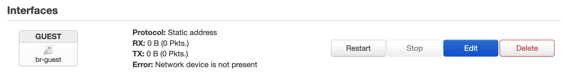
On the Web UI (LuCI) you should now see under Network->Interfaces a new Guest network. All of the changes landed in the /etc/config/network file.
Now we setup a wireless network configuration with the first radio
|
|
# Configure wireless WIFI_DEV="$(uci get wireless.@wifi-iface[0].device)" uci -q delete wireless.guest uci set wireless.guest="wifi-iface" uci set wireless.guest.device="${WIFI_DEV}" uci set wireless.guest.mode="ap" uci set wireless.guest.network="guest" uci set wireless.guest.ssid="mynetwork-guest" uci set wireless.guest.encryption="psk2" uci set wireless.guest.key="Friend Secret" uci set wireless.guest.isolate="1" uci commit wireless wifi reload |
Again, I’ve pretty much followed the directions but have customized the SSID and not shared the password. I’ve rolled in the extras to isolate guest users and use encryption.
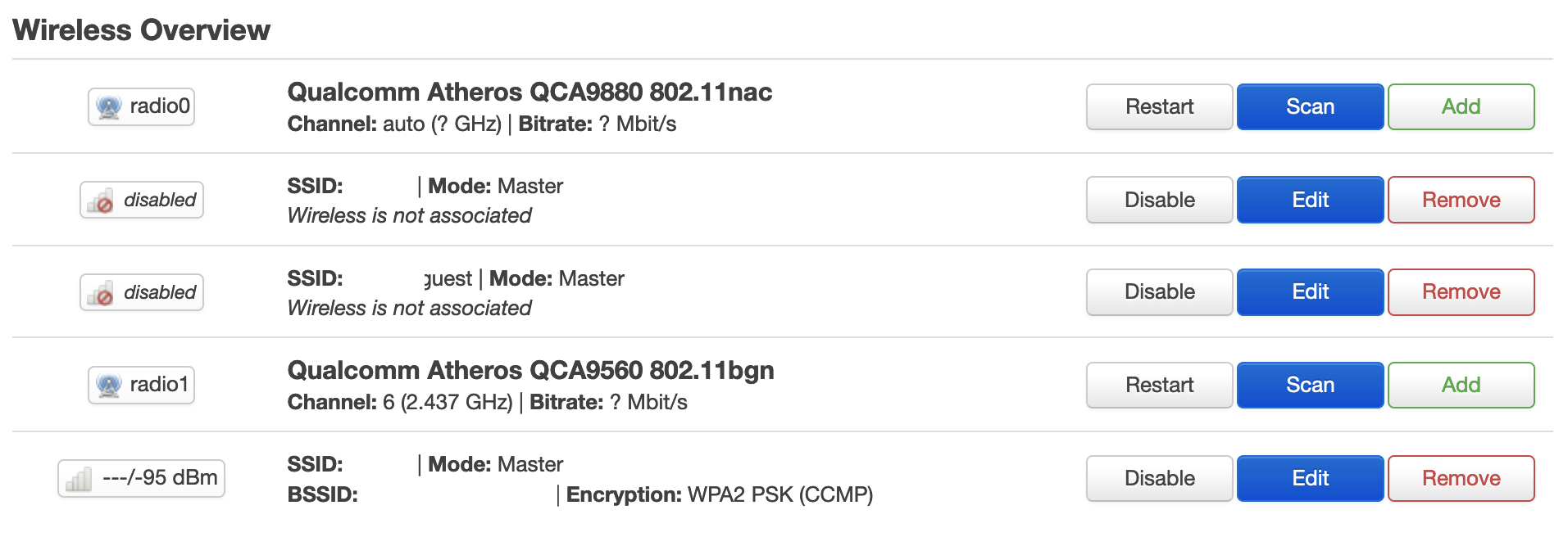
The LuCI web UI now looks a little more concerning (Network->Wireless)
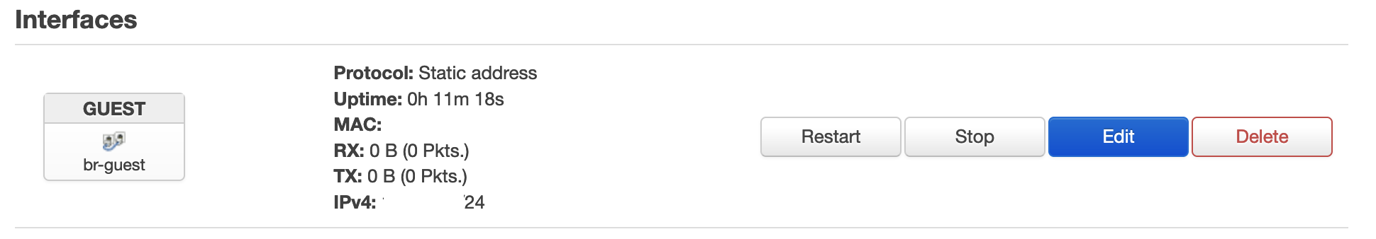
But.. the previous Network->Interfaces now seems to have come to life.
Still the expected changes are reflected in /etc/config/wireless.
It took a bit of head-scratching, but I figured out what was wrong. I had not specified a wireless.guest.key that met the minimum length (8 to 63 characters) – this apparently caused everything to go sideways. Once I fixed this my new wireless interface came to life.
Let’s continue on with the DHCP configuration
|
|
# Configure DHCP uci -q delete dhcp.guest uci set dhcp.guest="dhcp" uci set dhcp.guest.interface="guest" uci set dhcp.guest.start="100" uci set dhcp.guest.limit="150" uci set dhcp.guest.leasetime="1h" uci commit dhcp /etc/init.d/dnsmasq restart |
And the Firewall
1 2 3 4 5 6 7 8 9 10 11 12 13 14 15 16 17 18 19 20 21 22 23 24 25 26 27 28 29 |
# Configure firewall uci -q delete firewall.guest uci set firewall.guest="zone" uci set firewall.guest.name="guest" uci set firewall.guest.network="guest" uci set firewall.guest.input="REJECT" uci set firewall.guest.output="ACCEPT" uci set firewall.guest.forward="REJECT" uci -q delete firewall.guest_wan uci set firewall.guest_wan="forwarding" uci set firewall.guest_wan.src="guest" uci set firewall.guest_wan.dest="wan" uci -q delete firewall.guest_dns uci set firewall.guest_dns="rule" uci set firewall.guest_dns.name="Allow-DNS-Guest" uci set firewall.guest_dns.src="guest" uci set firewall.guest_dns.dest_port="53" uci set firewall.guest_dns.proto="tcp udp" uci set firewall.guest_dns.target="ACCEPT" uci -q delete firewall.guest_dhcp uci set firewall.guest_dhcp="rule" uci set firewall.guest_dhcp.name="Allow-DHCP-Guest" uci set firewall.guest_dhcp.src="guest" uci set firewall.guest_dhcp.dest_port="67" uci set firewall.guest_dhcp.proto="udp" uci set firewall.guest_dhcp.family="ipv4" uci set firewall.guest_dhcp.target="ACCEPT" uci commit firewall /etc/init.d/firewall restart |
Now not only should you be able to see the new WiFi SSID available to connect to, but when you do you will be isolated from all other devices on the network and only able to see the internet. A network scan will turn up the existence of the router, but attempts to connect the web UI fail – that’s pretty cool isolation.
Devices connected to the guest network still show up in the OpenWRT status page. They are assigned a DHCP address from the network.guest.ipaddr subnet, which is distinct from my normal network.
Apparently I do give up a little performance having two (or more) networks hung off of the same radio, but the utility of having a restrictive guest network is pretty cool.
The Archer C7 has two radios, and we’ve not configured the guest network on the second radio. Let’s do that now.
1 2 3 4 5 6 7 8 9 10 11 12 13 14 15 16 17 18 19 20 21 22 23 24 25 26 |
# RE-Configure wireless uci -q delete wireless.guest # Create a guest0 for radio0 WIFI_DEV="$(uci get wireless.@wifi-iface[0].device)" uci -q delete wireless.guest0 uci set wireless.guest0="wifi-iface" uci set wireless.guest0.device="${WIFI_DEV}" uci set wireless.guest0.mode="ap" uci set wireless.guest0.network="guest" uci set wireless.guest0.ssid="mynetwork-guest" uci set wireless.guest0.encryption="psk2" uci set wireless.guest0.key="Friend Secret" uci set wireless.guest0.isolate="1" # And a second one for radio1 WIFI_DEV="$(uci get wireless.@wifi-iface[1].device)" uci -q delete wireless.guest1 uci set wireless.guest1="wifi-iface" uci set wireless.guest1.device="${WIFI_DEV}" uci set wireless.guest1.mode="ap" uci set wireless.guest1.network="guest" uci set wireless.guest1.ssid="mynetwork-guest" uci set wireless.guest1.encryption="psk2" uci set wireless.guest1.key="Friend Secret" uci set wireless.guest1.isolate="1" uci commit wireless wifi reload |
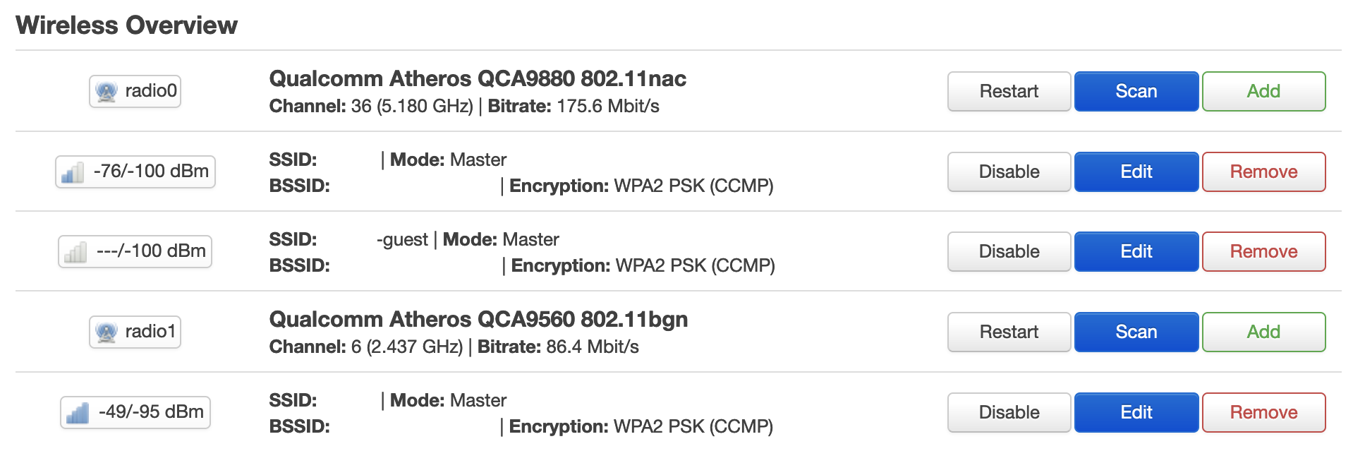
Cool – now I have a guest network that is on both radio bands. You’ll note that I run both access points with the same SSID, this mostly just works and devices figure it out. I even run my dumb AP with the same SSID. This is one approach that works and let’s people move around the house with seamless connections.
I do know that some people try to force a device to a particular radio type, and will run their legacy network on a different SSID. This is of course also valid, it really depends what you’re looking to achieve. I’m taking the simple to configure devices approach, and giving the devices the responsibility to work out which radio band and which access point to connect to.
Now let’s create a second ‘guest’ like network for IoT devices. This time I’ll just combine all of the steps together
1 2 3 4 5 6 7 8 9 10 11 12 13 14 15 16 17 18 19 20 21 22 23 24 25 26 27 28 29 30 31 32 33 34 35 36 37 38 39 40 41 42 43 44 45 46 47 48 49 50 51 52 53 54 55 56 57 58 59 60 61 62 63 64 65 66 |
# Configure network uci -q delete network.iot_dev uci set network.iot_dev="device" uci set network.iot_dev.type="bridge" uci set network.iot_dev.name="br-iot" uci -q delete network.iot uci set network.iot="interface" uci set network.iot.proto="static" uci set network.iot.device="br-iot" uci set network.iot.ipaddr="192.168.4.1" uci set network.iot.netmask="255.255.255.0" uci commit network /etc/init.d/network restart # Configure wireless - but only radio1 because that’s the old 2.4 and most IoT things live there uci -q delete wireless.iot uci set wireless.iot="wifi-iface" uci set wireless.iot.device="radio1" uci set wireless.iot.mode="ap" uci set wireless.iot.network="iot" uci set wireless.iot.ssid="mynetwork-iot" uci set wireless.iot.encryption="psk2" uci set wireless.iot.key="IoT Secret Key" uci set wireless.iot.isolate="1" uci commit wireless wifi reload # Configure DHCP uci -q delete dhcp.iot uci set dhcp.iot="dhcp" uci set dhcp.iot.interface="iot" uci set dhcp.iot.start="100" uci set dhcp.iot.limit="150" uci set dhcp.iot.leasetime="24h" uci commit dhcp /etc/init.d/dnsmasq restart # Configure firewall uci -q delete firewall.iot uci set firewall.iot="zone" uci set firewall.iot.name="iot" uci set firewall.iot.network="iot" uci set firewall.iot.input="REJECT" uci set firewall.iot.output="ACCEPT" uci set firewall.iot.forward="REJECT" uci -q delete firewall.iot_wan uci set firewall.iot_wan="forwarding" uci set firewall.iot_wan.src="iot" uci set firewall.iot_wan.dest="wan" uci -q delete firewall.iot_dns uci set firewall.iot_dns="rule" uci set firewall.iot_dns.name="Allow-DNS-IoT" uci set firewall.iot_dns.src="iot" uci set firewall.iot_dns.dest_port="53" uci set firewall.iot_dns.proto="tcp udp" uci set firewall.iot_dns.target="ACCEPT" uci -q delete firewall.iot_dhcp uci set firewall.iot_dhcp="rule" uci set firewall.iot_dhcp.name="Allow-DHCP-IoT" uci set firewall.iot_dhcp.src="iot" uci set firewall.iot_dhcp.dest_port="67" uci set firewall.iot_dhcp.proto="udp" uci set firewall.iot_dhcp.family="ipv4" uci set firewall.iot_dhcp.target="ACCEPT" uci commit firewall /etc/init.d/firewall restart |
Nice – now I have a third subnet which will hand out DHCP addresses valid for 24hrs. The devices are all isolated from each other.
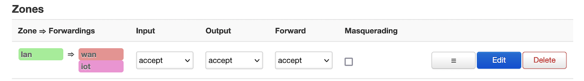
For devices on the IoT network, while I don’t want the device to be able to see anything other than the internet – for my own monitoring and use, I’d like to be able to see the devices on the IoT network from my normal lan network. This turns out to be very easy.
|
|
# Allow the lan to see iot, but not the other way around uci -q delete firewall.lan_iot uci set firewall.lan_iot="forwarding" uci set firewall.lan_iot.src="lan" uci set firewall.lan_iot.dest="iot" uci commit firewall /etc/init.d/firewall restart |
Connecting to the IoT network and doing as scan, shows me that I can only see myself and the router (because the device has to send traffic somewhere). Again, with the isolation I can’t connect to the web interface of the router. However, with this new “zone->forwardings” I can from my lan network see devices on the IoT network. Super cool, and actually very easy.
There plenty more tweaking we can do here, but to avoid going too far down the rabbit hole we’ll stop here.

 Using
Using