I’ve had my eye on the TED device for quite some time. It allows you to monitor your power consumption at the whole house level. I’ve used in the past a Kill-A-Watt which is handy to monitor energy usage by a single device.
The TED 1000 had a closed software package, but showed promise. The TED 5000 provides a web based API to both view your data – and provides a manner to export it. The TED 5000 is one of the few devices supported by Google Powermeter, while I don’t plan to make use of the Google service I do hope they figure out how to collaborate with the community better.
Ontario has a Smart Meter plan on the way, but the roll out is taking a while and I really don’t trust them to get the web tools right in the near term. The TED 5000 is available now, and the data is easy to get to if I want to re-graph it in some way.
I ordered the basic package (TED 5000-G) – there are two basic parts that come with it. The MTU (Measuring Transmitting Unit) and the Gateway, each packaged in their own little box. The first (and scary part) is installing the MTU as it it attached to your electrical panel. The MTU communicates over the power lines to the Gateway (no need to run wires from one to the other). The Gateway needs to be plugged into your router/network and will aquire an IP address via DHCP. You interact with the Gateway with a web browser to view/configure the data.
The rest of this posting is about the install procedure, read on for gory details.
Disclaimer: This article will cover an activity that will expose you to deadly levels of electrical current. YOU COULD DIE. I will strongly urge you to hire an electrician to perform this procedure.
The instructions that come with the TED 5000 on the installation are not terribly clear. I spent an hour reading and re-reading them to ensure I had it straight in my head. Working in the dark by flashlight with high voltages exposed, you want to know what you’re trying to accomplish. The best resource came on the mini-CD – a PDF called “TED 5000 Installation Pictorial.pdf”.
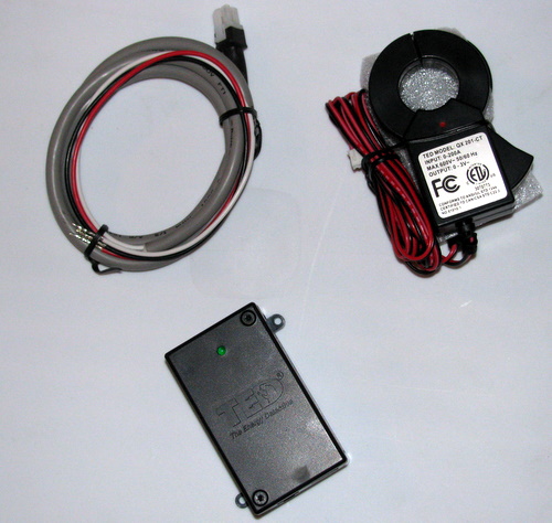
Pictured above is the power cable for the MTU, 2 Current Transformers, and the MTU itself.
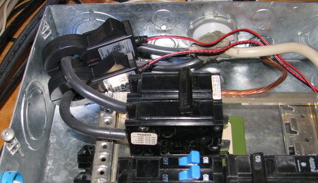
The Curent Transformers (CT’s) are clipped onto the incoming power lines. If you look very closely at the CTs you will see a red dot on them.  This dot indicates the polarity of the CT and both must be pointing in the same direction (both towards the panels circuit breaker, or both away). The direction here is the flow of electricity, not the absolute orientation.
The power cable has three wires: red, black, white. This will be attached your panel to draw power and provide a communication path for the MTU. The white should be attached to the neutral bus, the red to one circuit breaker and the black to another on the other phase. The point here is to create a 240V circuit, you must not connect the red and black to the same phase.
Another Disclaimer: If you are at all unsure about how your electrical panel works, please seriously consider having a professional do this.
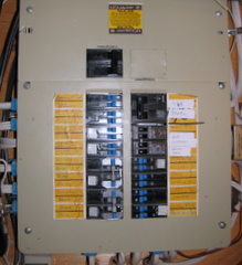
Now let’s take a look at my electrical panel.
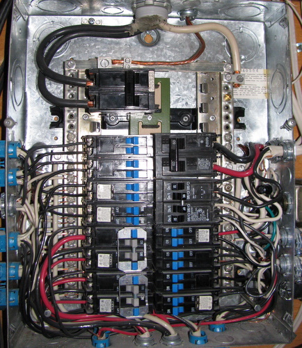
The first picture on the left is the panel closed, and in operation. If you look carefully at the master breaker at the top you can see it is in the “on” position. The second picture on the right shows that same breaker in the “off” position, and the cover removed. Since the master breaker is off, all of the exposed wiring should be safe to work on. It is in this exposed area we will be attaching the MTU power cable.
Unfortunately the CTs need to be clipped around the incoming power lines. Thus we must open the top portion of the panel exposing live wires. This is the scary part. You’ll likely standing in the dark with a flashlight, trying to clip these CTs around the two big black wires.
Once you succeed at doing this, double check that the red dots are pointing in the same direction. Carefully route the wires from the CTs down to where you’ll be hooking up the MTU. Then immediately replace the top portion of the panel, returning things to a “safer” state.
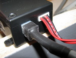 I found that there wasn’t room in my panel to place the MTU, so I ended up running both the CT wires and the MTU power cable out via a wire clamp and locating the MTU next to my panel. I mention this detail because it sent me running off the my workshop (in the dark) to find a clamp.
Once you have the wires sorted out, connecting them to the MTU is trivial. The power cable has a very positive orientation – you can’t get it wrong. The CTs connection is a bit trickier to figure out, but once you take a close look it should be self evident. This is something you may want to examine prior to working in the dark via flashlight.
Once you have closed the panel and then restored power, the MTU will blink the LED every few seconds. This indicates it is functioning correctly and is sending data out over the power lines to the Gateway.
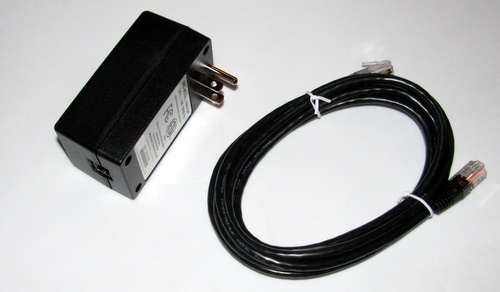
The Gateway comes boxed with a nice ethernet cable. You need to connect the cable between the Gateway and your network. However, there is a trick here and it caused me some grief. The power line transmission is sensitive to noise on the power line. Switching power supplies (ie: computers) cause a lot of noise on the power lines. My initial attempt to plug it in next to my server failed, as the Gateway was not receiving a clean enough signal from the MTU.
There is a useful troubleshooting guide, but this is easy to check. Simply plug the Gateway into an outlet, wait a few seconds for it to bootstrap (ignore the series of flashes during this time) then watch the LED on the side – it will blink green every few seconds if it is receiving from the MTU. In my case I was able to get a good signal from a nearby outlet (one with no computers on).
That’s it – you’re ready to go. There is a firmware update required to use the Google Powermeter stuff. I’ll likely post more once I figure out what to do with this new data source.


Cool, will get mine Monday from work. Not sure when I’ll get time to look at it and when I can disconnect the house from power. It’s dark at night these days.
Any update on how the TED 5000 is working for you?
The TED 5000 continues to work well for me. I’ve been meaning to build my own graphing software as the stock stuff is not really great.
There have been a couple of times when the gateway has lost its configuration and it needed to be reconfigured, but it wasn’t a big deal.
Check out my sort of related post: http://www.lowtek.ca/roo/2010/earth-hour/
Have recently installed TED5000 and it is working great. I am searching for compatible software for home PC. As you pointed out, the software that comes with TED5000 “is not great”. Have you found anything better?
I have looked at on-line stuff (myEragy, Bidgely, PlotWatt) but find them incomplete.
Thanks.
Bill, I keep meaning to invest some time into fixing up some software to monitor/plot the TED 5000. It’s one of those things that’s pretty far down on my list however.
You’ve likely come across http://www.theenergydetective.com/third-party-apps which is a good starting point.
If you’re at all handy at programming, the data is easily available: http:///api/LiveData.xml – you may also want to refer to the API http://files.theenergydetective.com/docs/TED5000-API-R330.pdf
My personal preference would be to have a light-weight app that could run locally, or on my personal web server.