I needed some more home automation friendly outlets, and my preferred Sonoff S31 outlets are hard to get at the moment. It also seems that the S40 has been released as a replacement, but moves away from the ESP micro-controller. This got me looking for what I could get locally.
The Home Depot carries the Defiant series, which when I looked up the details on the FCC website it seemed like a great candidate having an ESP32 inside. However, it seems that the eFuse has been flipped to prevent any further firmware updates. I then moved on and found a sale price of $22.99 for a 3 pack of the Globe Electric Smart Plugs.
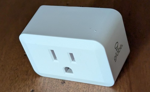
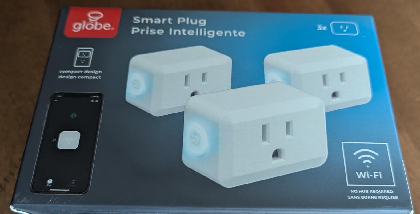 Now these plugs do not have an ESP device in them, but a WB2S module. Some folks take advantage of the fact that this is pin compatible with an ESP device and will just swap in a whole new logic board. However, you can also use OpenBeken which I’ve done before. Since these were pretty cheap I picked up 3 boxes (9 plugs).
These plugs are fairly compact and you can fit two in an outlet (top and bottom) if you wanted.
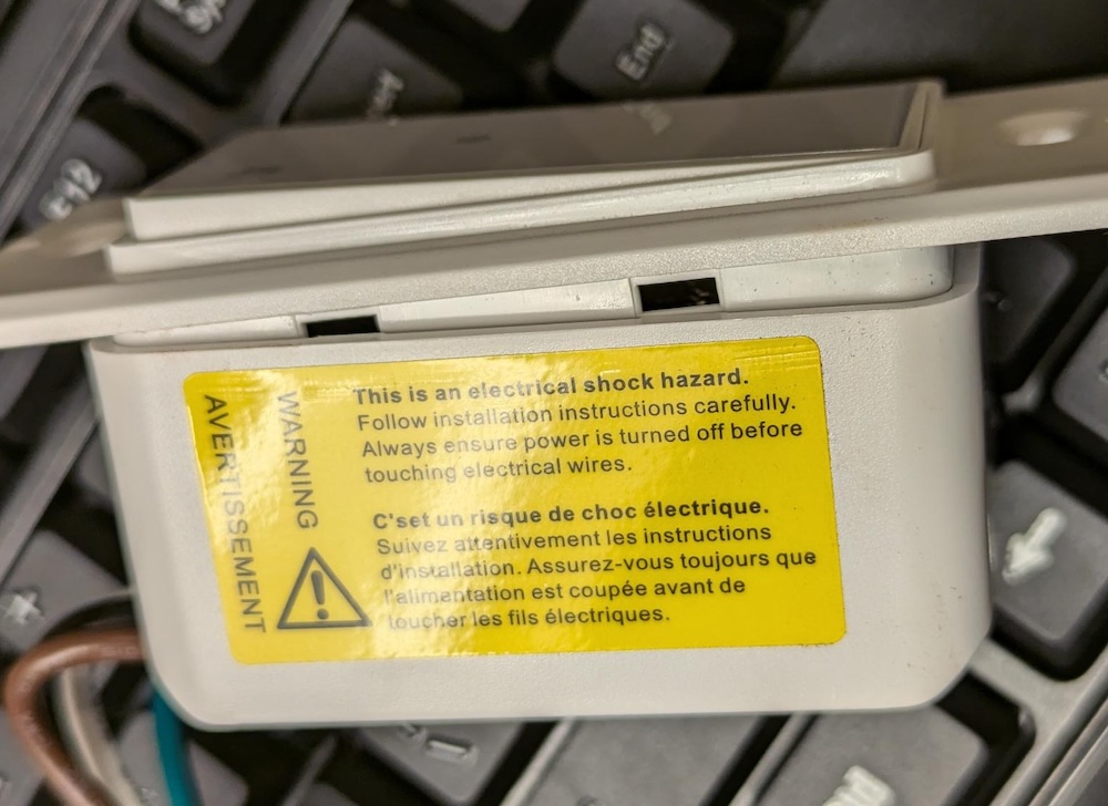
 The first thing we need to do is open these. This is fairly easily done using a pocket knife and a little bit of patience / prying. After doing a few of these I got pretty quick, a minute or two to open them. I captured a short video I put up on YouTube showing this process.
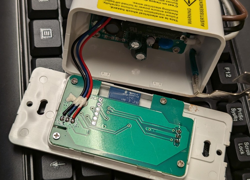
 Now that it’s open, you can remove the exterior case entirely and you have access to the internals. The micro-controller was easy to spot, it is on it’s own tiny circuit board.
 You can see why some folks are simply removing the entire controller board and swapping in a compatible one with a more friendly chip to program. However, with OpenBeken we have the option of reprogramming this chip with some firmware to give us local only control (via Home Assistant).
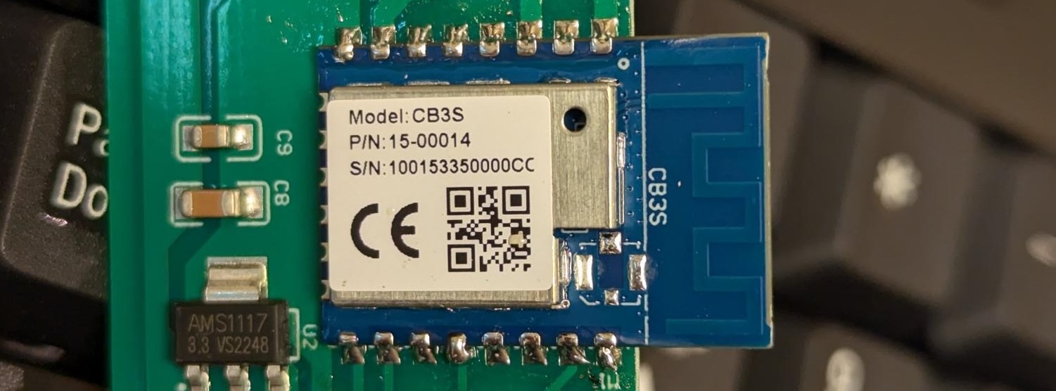
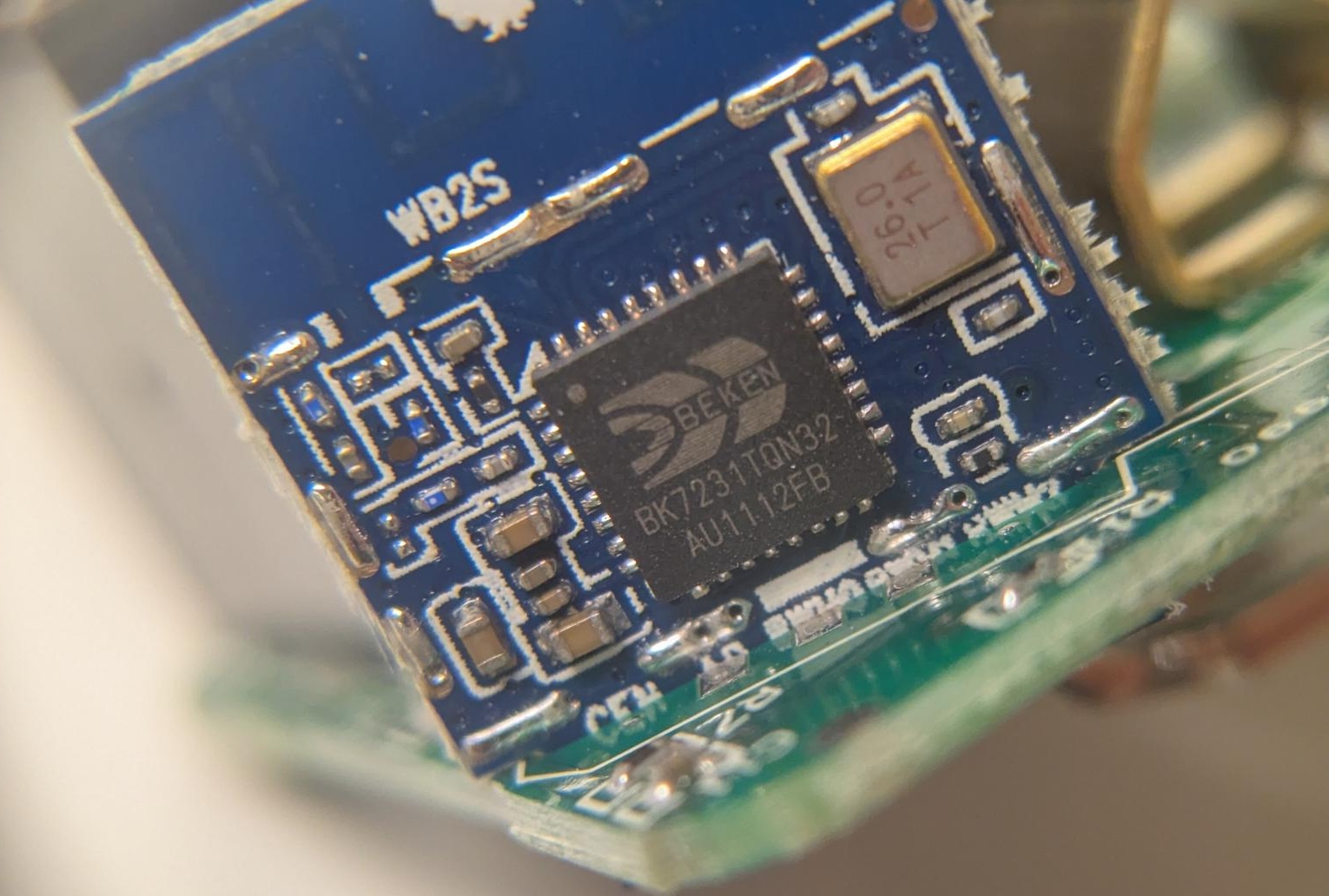
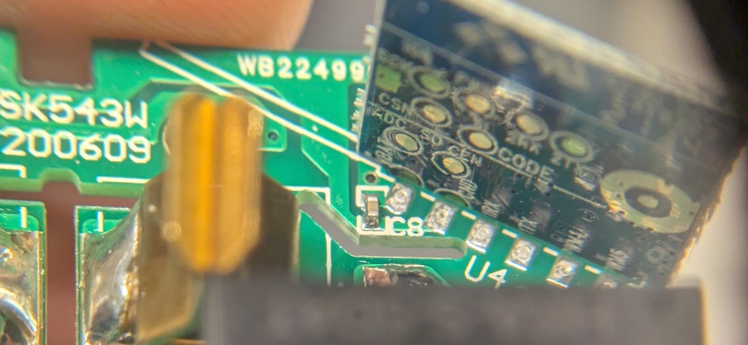
At the top you can see this is a WB2S board, and the chip is a BK7231TQN32. For the most part this chip is referred to as a BK7231T.
We’re going to need to hook up 4 wires to this to reprogram it, 3.3V, GND, Tx and Rx. Let’s figure out where those pins are.
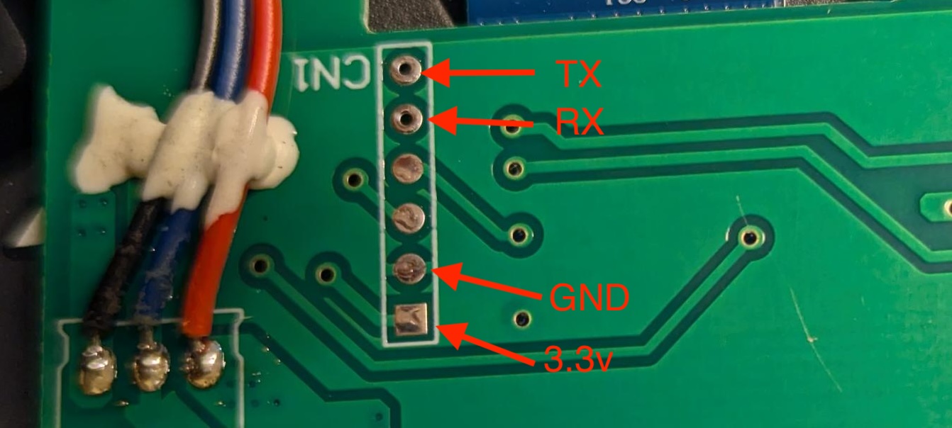
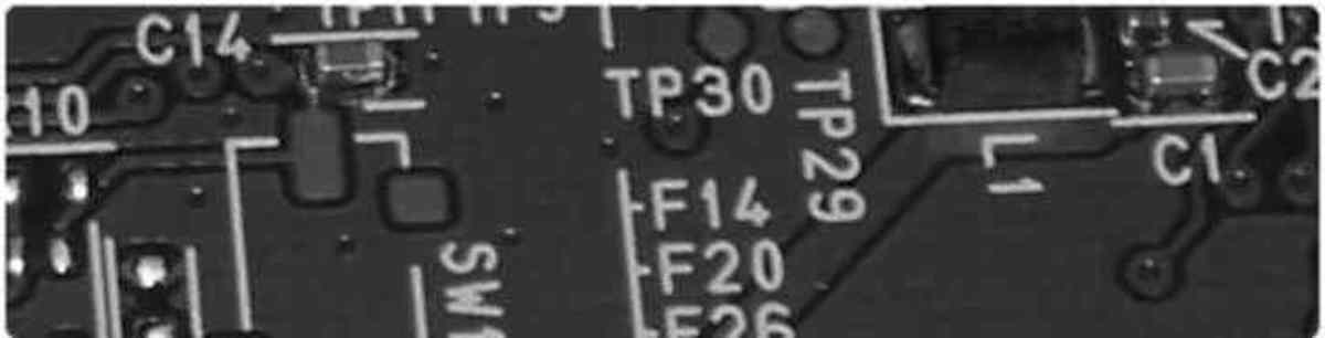
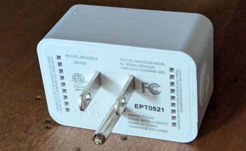
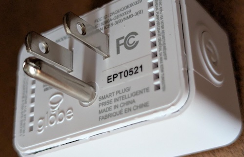
 This is the other side of the board, and if you look carefully you can see at the bottom edge we have starting from the left side BAT, GND, IRX, ITX. These are the 4 pins we need to connect with. Thankfully we can access each of these from the bottom side of the board as the controller board slots into the main circuit board on it’s edge.
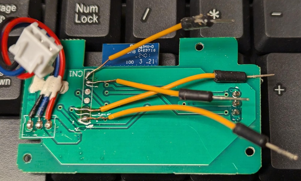
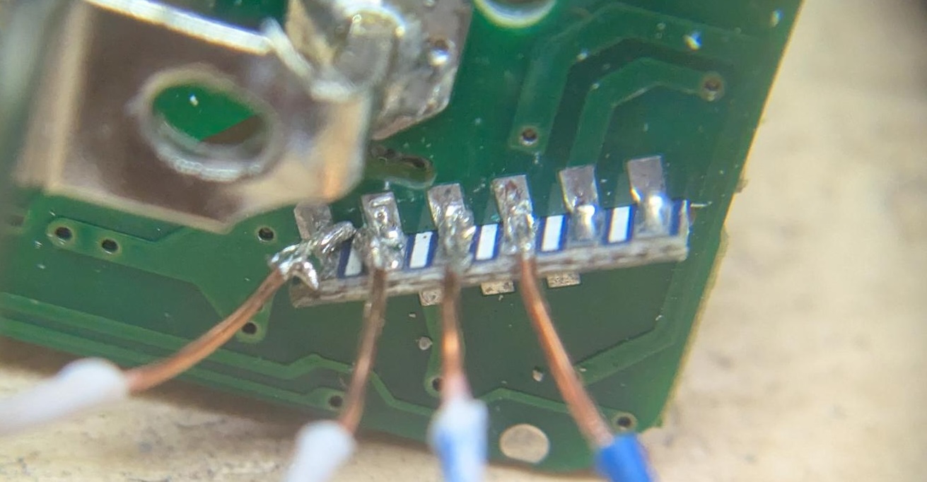 Not very pretty, but it gets the job done. The wires are from some stripped ethernet cable and I think they are 26AWG – fairly small. While this was convenient for me to connect some wires to, upon inspection it seems the only reason there is any solder here is to support the board-to-board connection, I’m pretty sure all of the actual interfacing to the circuits is on the other side.
Someone on the Elektroda forum seems to have done the first work on one of these plugs. A lot of people using OpenBeken have used the CloudCutter project to reprogram things without wiring anything up, but this seemed more complicated to me and not guaranteed to work with all devices.
My first attempt I used the same software as I had previously. The only change was to download a different firmware because this is a different module. Unfortunately I goofed somewhere and when flashing the device it failed, then it was no longer responsive to my attempts to connect via serial at all. It may be a brick now, boo.
For my second attempt, I did more reading about the ESPHome support for BK72xx chips. There is quite detailed information about flashing the chips, and it seems to strongly recommend you do not use the old tool I had previously used. There is also a section there on un-bricking things which I’ll have to try later.
Thus I picked the ltchiptool – and installed it under Windows. The easy way to do this on Windows was use the Microsoft Store to install “Python 3.10” – then run pip install ltchiptool[gui]
Once installed, you can launch the GUI with python -m ltchiptool gui
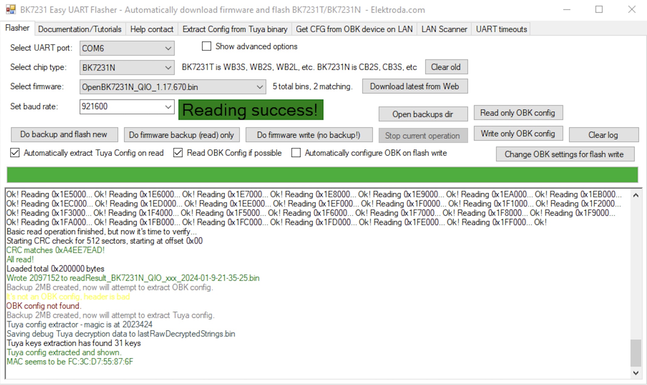
While I may eventually end up using ESPHome, I decided to stick with OpenBeken and grabbed the latest OpenBK7231T_UA_1.17.800.bin from their download page. I first used the ltchiptool to download the existing flash image to confirm my wiring was working. Then I held my breath and uploaded the firmware.. and it worked.
Then it was a simple matter of repeating things. Crack open the case. Solder some wires. Hook it up to ltchiptool, download to confirm things are working, upload new firmware. De-solder the wires. Re-assemble. Now I had 8 outlets reprogrammed.
A dab of crazy glue helped re-seal the exterior cases. So far this seems just fine after a few insert / removals of the plugs.
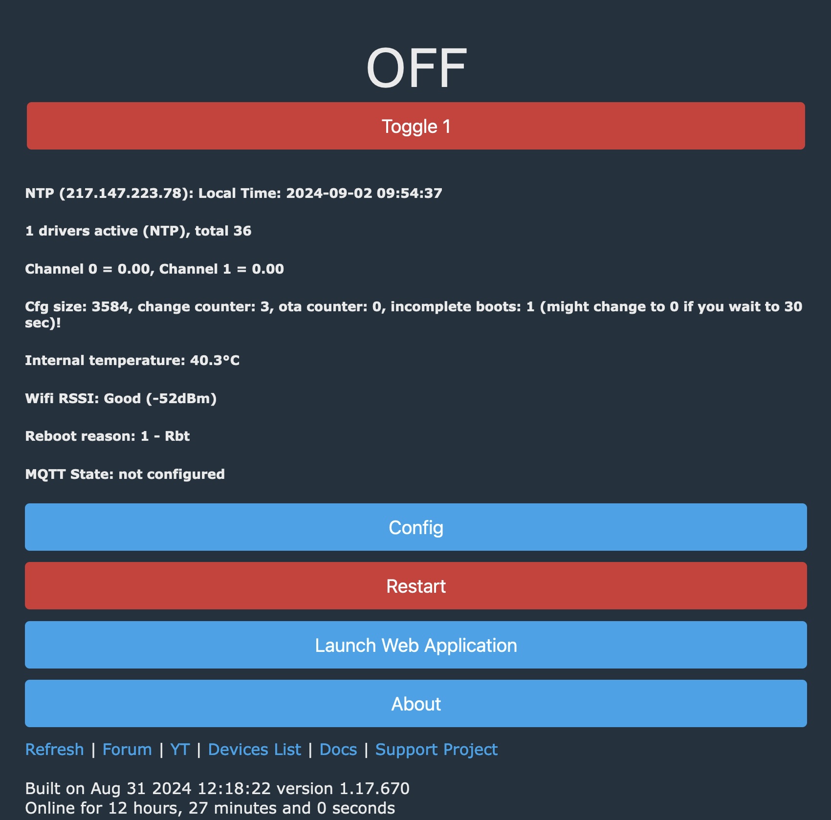
Next we need to do some configuration. Upon first boot the device will offer up a captive portal. Connect your computer to the “OpenBK76231N_XXXXX” WiFi and visit http://192.168.4.1 in a browser. From here we can pick “Config” then “Configure Wifi & Web” to setup the Wifi connection.
Once the device is on our WiFi network, it can then see the internet which allows us to use the “Web Application” to further configure the device. You can launch the Web Application from the main landing page. I did find that it was important to access the device via IP address (ie: http://192.168.1.56) vs. by name.
 Once we launch the Web Application, we can easily configure the device by using the “Config” tab, and searching for the right template from the web. I have to say this is a pretty clever way to do things.
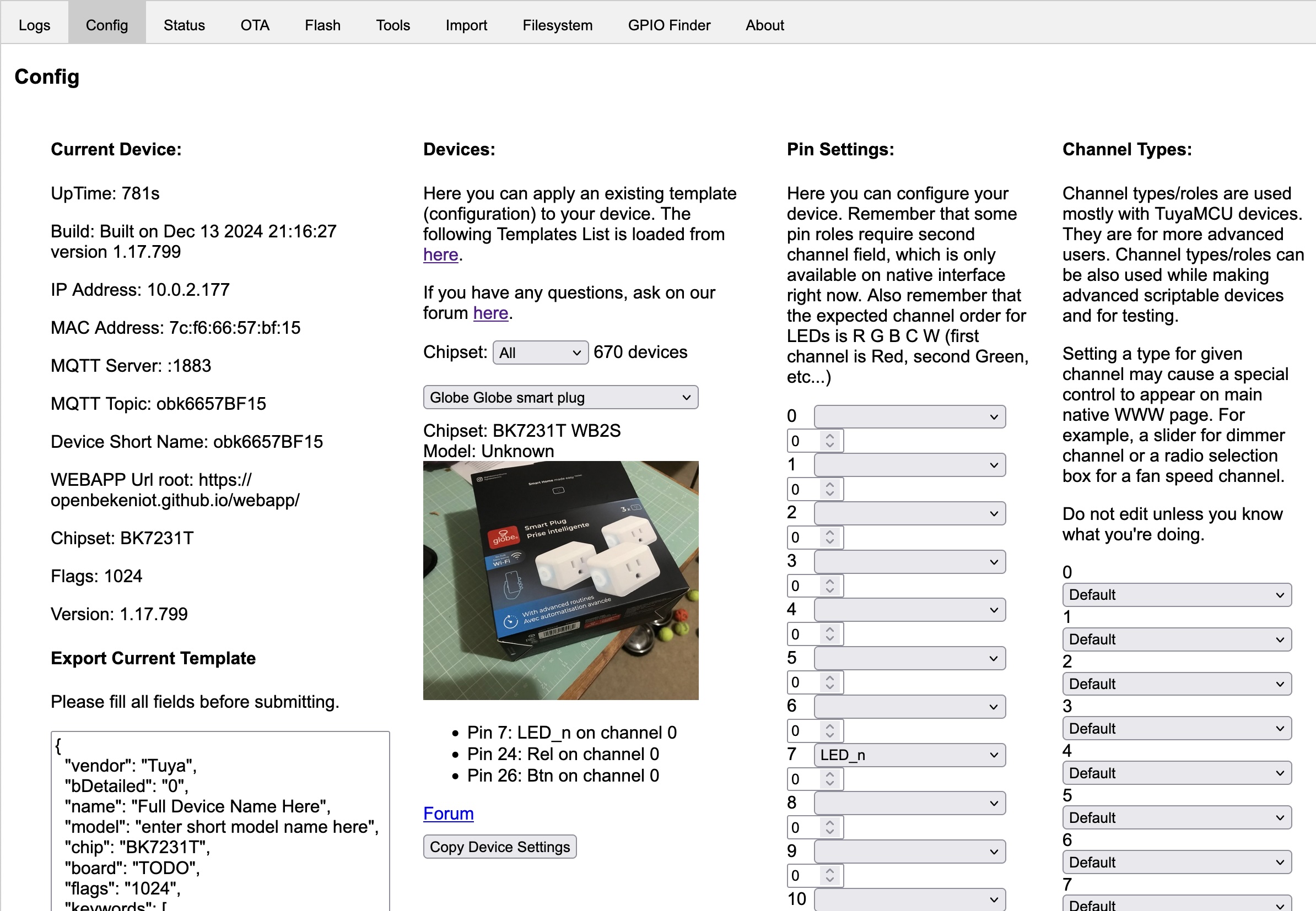 You can see I’ve searched up the “Globe Globe smart plug” and have used “Copy Device Settings” to populate the “Pin Settings”. At the bottom of the page there is a “Save” button to persist the choice. Now if we revisit the Home page we will see the device now offers up control of the power. The button on the side of the plug also now works to toggle power.
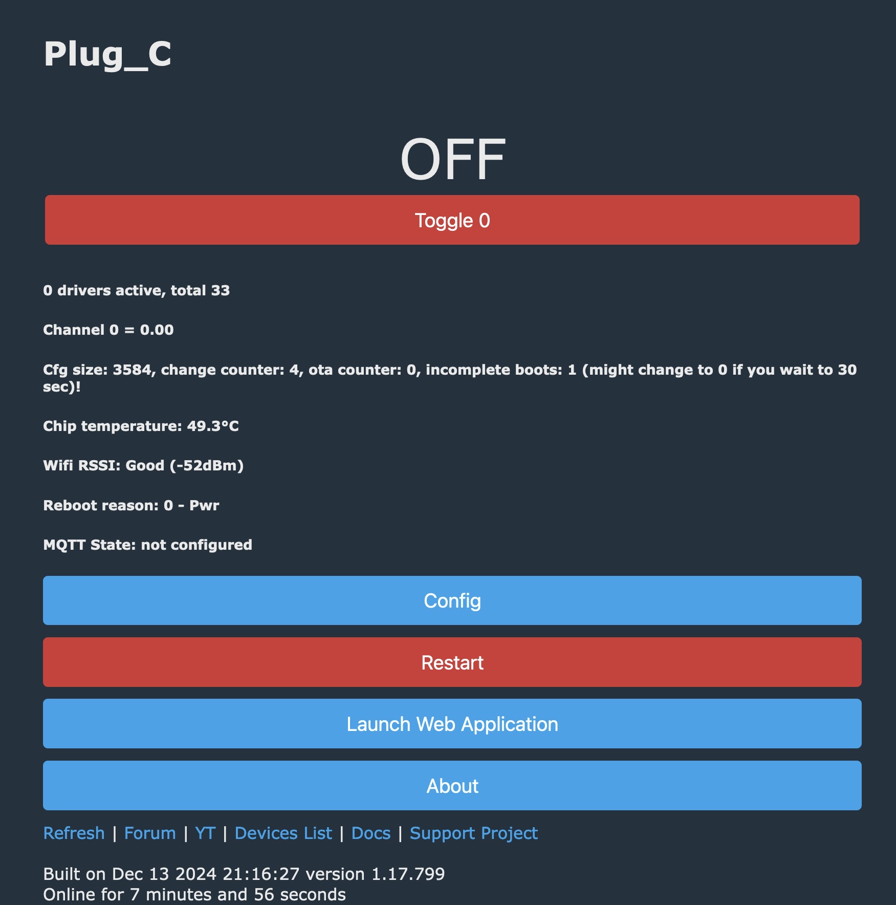 The last thing we’ll do is connect this up to Home Assistant. The easy path here is to setup MQTT (Config->Configure MQTT) and get connect to your broker. I was left scratching my head why Home Assistant wouldn’t see these new devices – and after a lot of probing around my MQTT setup and verifying that data was flowing, I finally watched the video the explains it.
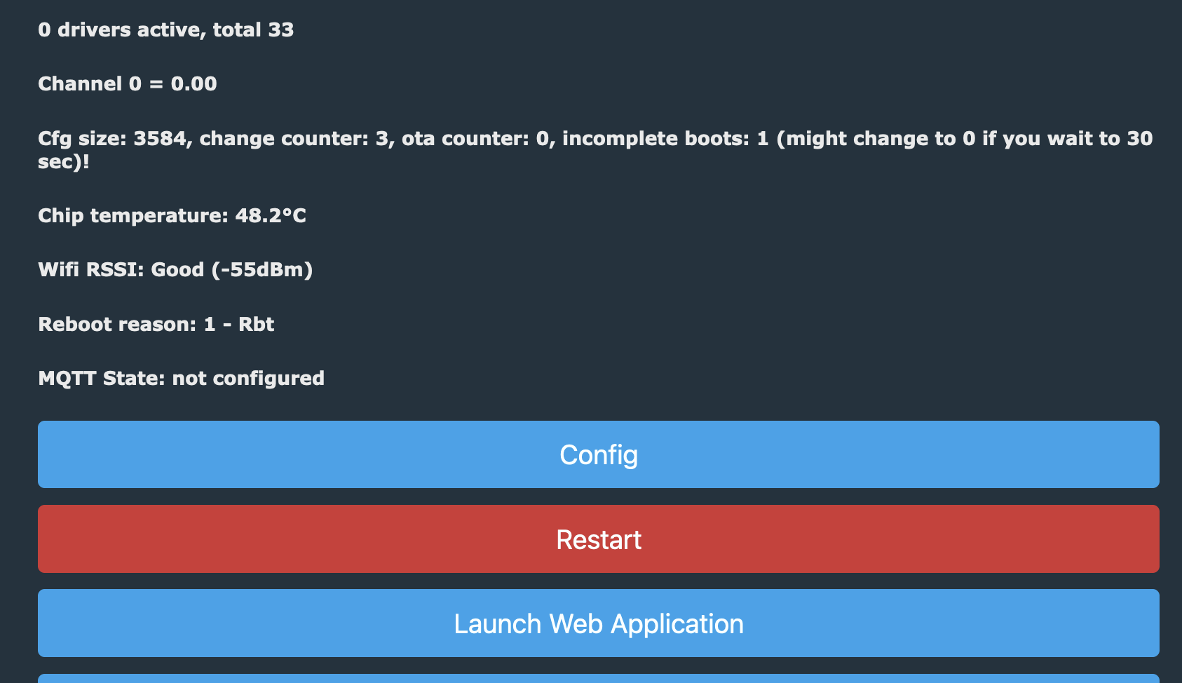
Short story was – after you’ve got MQTT setup, and the main page will show you the MQTT State is connected – you need to do one more thing to have it emit a discovery payload to Home Assistant. (Config->Home Assistant Configuration) and hit “Start Home Assistant Discovery”. Then the devices just appeared with their short name in Home Assistant.