Arduboy Developer Kit

arduboy

When I saw Arduboy on KickStarter I knew I had to get a couple. Micro-controllers & retro-gaming in a teeny-tiny package. The KickStarter rewards haven’t shipped yet, but when I saw that there were going to be Dev kits available on tindie I leapt at the chance to get my hands on some hardware. I’m really glad they decided to make more Dev kits than were needed to fulfil the Kickstarter.

While the device can be run on a CR 2016 battery, it will also power up via micro-USB cable. The device ships with a breakout game (ArduBreakout) installed, so you just have to power it on to have some black & white retro gaming fun.

So now what? Well, of course we want to get setup to write some code and run it on this thing. Luckily there is a community site with instructions.

My desktop is Ubuntu, so here’s what I needed to do:

Then you’ll want to go to GitHub to grab the Arduboy library and some examples.

Launch the Arudino IDE and load up one of the examples (FloatyBall, a Flappy Bird game)

Before this code will compile – there are 3 things you’ll need to do

  1. Add the Arduboy library files to the Arduino IDE
    Sketch -> Import Library -> Add Library
    If you don’t do this, you’ll get an error saying Arduboy.h can’t be found.
  2. Set Leonardo as the target
    Tools->Board->Arduino Leonardo
    Using the wrong board will result in errors like: “error: ‘OCIE3A’ was not declared in this scope TIMSK3 &= ~(1 << OCIE3A);”
  3. Select the correct serial port
    Tools->Serial Port->/dev/ttyACM0
    When I hadn’t done this, the led on the board would flash like it was uploading, but then I’d get an error saying it couldn’t upload

At this point I just wanted to stay up all night hacking code..

More games can be found on the community site.


Replacing iPhone 4 screen

IMG_2839


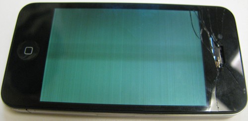
I had the chance to help out with a neighbours iPhone 4 that had a broken screen. This gave me an excuse to pick up the pentalobe screwdriver to add to my collection of useful tools. The phone came to me in the state shown at the top of this post, the screen would light and you’d get lines as the image but the touch functions seems to be non-responsive. The phone was still working and you’d hear text message notifications and the like, I didn’t bother to plug it into a PC but I’m certain you could still sync it to a PC.

IMG_2842


The pentalobe screwdriver is essential for opening up the iPhone. Those screws are really, really small. Disassembly is pretty straight forward, I made use of a pair of YouTube videos to help me out: the first video covers both tear down and rebuild; the second one is shorter and covers only the tear down.

Immediately after removing the back cover, I was amused to find the following warning:

IMG_2843


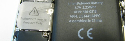
If you’ve gone to the trouble of removing those darn screws, is a little plastic tab with a warning really going to deter you? At this point in the disassembly I started to get the feeling that I wasn’t the first person to have ventured inside of this phone. The plastic tab with the warning actually was busted off already, the battery wasn’t very tightly glued in and the water damage dot was entirely missing.

Once you’re inside the back cover a small Phillips screwdriver will handle almost all the screws. In my case the correct sized Phillips came along with the pentalobe. In the second video they talk about a single screw needing a small flat head jewellers screwdriver, this puzzled me until I got to that part of the disassembly. A rather ‘large’ small flat head is all I needed.

IMG_2848


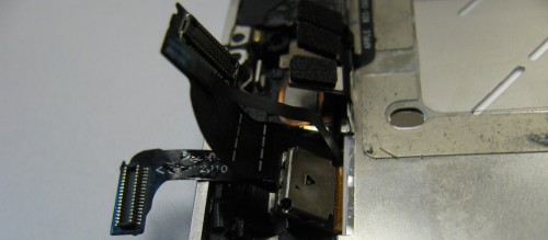
You can see the screw that needs this flat head in the center of the picture above, it’s looks like a big plus sign with a hole in the middle. The 3.5mm jack is visible in the picture.

To replace the screen you need to work your way through from the back of the phone to the front, this requires taking almost everything out of the phone. At this point it was clear that not only had someone been in this phone before, but that they had skipped over some of the reassembly steps. The screen should be fastened with 10 screws, this phone only had 7 and one of those that has a washer was missing the washer.

In my case, it turns out this phone had already had a replacement screen put in so there wasn’t any glue / stickiness holding the screen to the frame. Removing the two ribbon cables is a little fiddly, take your time and they’ll side out easily.

IMG_2856


Re-installing the screen be very careful of the ribbon cables. It is very easy to get them pinched behind if they are not pulled through completely. If you don’t have them complete through they will not stretch far enough to connect to the motherboard. There is barely any slack in the ribbon cables, so if they are not routed correctly they simply won’t reach. This is one of those things that you can’t rush and taking your time when doing the disassembly (and taking pictures) can be a big time saver when re-assembling.

This was the 1st time I’d done this type of repair and it took me a little over 2 hours. I did fail to get one of the screws to install, it felt like the hole had been stripped. I’m not sure this was me or the previous repair job, but I still was frustrated to have it happen. Oh yeah, and work on a surface that will help you find those tiny little screws, even if you drop them – I worked on the floor with really good lighting and no clutter around me.

Unfortunately a bit over a week later I was back inside the same phone. Apparently while it looked and worked fine once I was done, over the next couple of days it started to exhibit ‘strange’ behaviour: fuzzy screen, non-working screen. These problems could be resolved by giving the phone a whack, but sometimes the whack caused it to be worse. Finally after one whack too many the screen went dark and that was it. [Please, don’t whack things to fix them!]

I was hopeful that it was simply a loose connector, but after reseating the various connectors I wasn’t able to bring it back to life. The owner took the phone to a repair shop that replaced the screen again and commented that some of the ‘knock off’ replacement parts had this type of problem.

In summary – I can’t claim that I really fixed it, but it was fun taking the phone apart and putting it back together again. I’ve got the tools I need now, and the experience. I was also pleased to find out that the 4 / 4s screens are fairly cheap, even locally. The screen for the 5 is much more expensive.

Fixing a fake USB flash drive

IMG_2836


A couple of years ago I picked up a conference give-away flash drive (4GB), which at the time seemed like a pretty nice freebie. The trouble was it only every liked to play nice with my Windows machine, Linux would refuse to mount it. The headline photo is the final product, I failed to take a before picture but the leather + snap case on this USB thumb drive was hideous anyway.

Turns out it was a fake, good thing it was free. Still in my typical fashion I didn’t want to just throw it away, heck I’m still carrying around the mysterious AMD 1GB key I got ages ago. So this bogus 4GB key sat in my work bag for a long while before I finally got to investigating it.

The very first thing I did was use the linux command lsusb, this helped me clue in that there was something wrong (fake) with the drive. I found a forum post that helped me get started down the right path. I got a copy of ChipGenius which told me the following:


Description: [I:]USB Mass Storage Device(Generic Flash Disk)


Device Type: Mass Storage Device

Protocal Version: USB 2.00
Current Speed: High Speed
Max Current: 100mA

USB Device ID: VID = 0011 PID = 7788
Serial Number: 874BE199

Device Vendor: Generic
Device Name: Mass Storage
Device Revision: 0103

Manufacturer: Generic
Product Model: Flash Disk
Product Revision: 8.00

Controller Vendor: Alcor Micro
Controller Part-Number: SC708(FC8708)/AU6987 - F/W EC23
Flash ID code: ADD5949A - Hynix H27UAG8T2BTR - 1CE/Single Channel [MLC-8K] -> Total Capacity = 2GB

So this felt like progress: it's 2GB and not 4GB as Windows seems to think. Still not bad for free. I then used my camera to get some close up shots of the naked circuit board to confirm the data that the ChipGenius tool dug out.

IMG_2810

IMG_2806


It was good to see that the values matched, this helped boost my confidence in the ChipGenius tool. I did find some references on the web claiming that sometimes ChipGenius is wrong, so it’s worth looking at the chips themselves.

Part of the output was also a link to a website, yet even with google translate the site left me guessing as to what I wanted to download – there were a lot of possible options. I choose one near the top “Series master, the Alcor MPtool AU6987T/6989 Yasukuni, production tools (2011.12.26.00)” as the title matches some of the data in the ChipGenius dump. In the end the stability of the site, language barrier and my inability to successfully download anything sent me off down other paths.

I then ended up searching on flashboot.ru with the controller chip number (FC8708) I was able to find and download (with a bit of google translate help) a tool that recognized the drive. The best way to find this tool is searching it’s name: FC_MpTool_FC8308_FC8508_FC8406_04.02.01.

FC MpTool

The user interface was mysterious, but clicking on the drive letter started a reformat.. which resulted in a 2GB flash drive. This newly formatted drive was quite happy under Linux.

In terms of performance, I benchmarked copying 7 x ~300MB video files (total 1.9GB) to the stick, this reported ~4.7MB/sec. There were certainly bursty updates in file file progress dialog in Ubuntu. This isn’t great, but again it was free and it works under Linux. I also tried zeroing the entire drive ($ sudo dd if=/dev/zero of=/dev/sdc) which reported: 2095054848 bytes (2.1 GB) copied, 335.285 s, 6.2 MB/s – again, not great but good enough.

A bit of heat shrink tubing applied to cover up the bare circuit board and I’ve got a hack worthy USB key.