As I have mentioned in a previous posting, I use the Spyder2 sensor with the HCFR software for colour calibration.
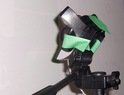
The Spyder2 isn’t actually intended for use with front projection systems, but in practice it works quite well. The first hurdle is tripod mounting the sensor which doesn’t come with a screw hole for the tripod. In the past I’ve used a little painters tape to hold it on.
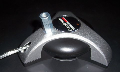
While this works fine, I’d much rather be able to screw it onto the tripod mount like I do my camera. It turns out that a standard 1/4″-20 nut will work just fine for this purpose, that an a little glue gives me a nice way to tripod mount the sensor.
There is a removable filter on the Spyder2, the documentation recommends using the filter for LCD displays (flat panel/computer monitors). In the past for CRT projector calibration I’ve removed it and aimed the sensor at the screen to record the reflected light. For my current LCD projector I’ve been leaving the filter on.
Tonight I experimented with the filter on, and off. With surprising results. I am using HCFR in its LCD mode, but I would have thought that would have minimal impact on the readings.
Filter On
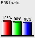
Filter Off
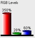
These readings are based on a 70 IRE gray screen, all I did was swap the filter on and off. The filter on measurement matches what I was seeing on screen, a mostly balanced gray.
From my experiments, there seems to be some minor variation in readings based on the angle of the sensor relative to screen surface, but only a few percentages. When pointing the sensor at the projector there is more variation, but it didn’t seem to be radically different.
When reflected from the screen, I have the projector ceiling mounted and the sensor pointing at an angle up toward the center of the screen. You can get a sense of what I mean by the first picture in this posting. When gather data on having the sensor pointed at the projector, I mounted it a few feet out from the screen, approximately centered and as perpendicular to the incoming light as I could manage by eye.
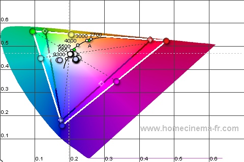
Here is the CIE diagram based on readings from the screen.
And here is the CIE diagram with the sensor pointing at the projector.
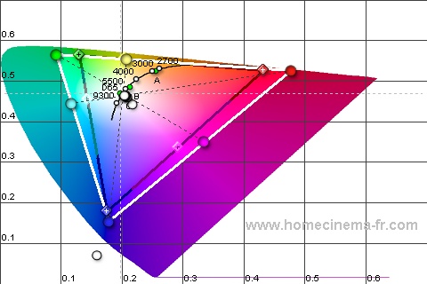
The CIE diagrams look nearly identical. Things get more interesting when we look at the RGB levels and delta E.
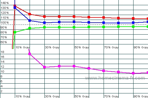
Here is the RGB levels as read from the screen.
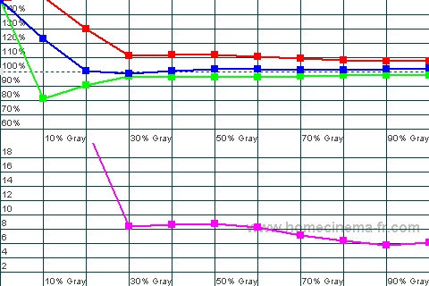
And now RGB with the sensor pointing at the projector.
By pointing at the projector, I’m able to get more sane looking reading down to 20IRE, whereas the reflected from the screen readings are only sane to 30IRE.
However, the delta E values are quite a bit higher when pointing at the projector. This may be due to higher variation in the readings due to the angle vis-a-vis the projector or that we are not taking into account the effect of the screen. It almost seems we are trading off accuracy for better low IRE response.
In conclusion:
- I’d highly recommend gluing a nut onto your Spyder2 sensor, it makes mounting it on a tripod really easy.
- Filter on seems to be the way to go, but I’d like to understand why I got such whacky readings with it off.
- Reflected off the screen seems to be the best solution for getting readings.
I posted this to AVSForum and it was pointed out that using HCFR in CRT mode would fix the whacky readings I got with the filter off. I will have to revisit this in CRT mode and see what the results look like.