Printrbot has been continuing to refine their printers as they go along. Since the original Simple beta, they’ve gone through a few revisions. The original didn’t have end stops, this now comes as part of the kit. A fan was added to help temperature control. They’ve added tension adjustment on the strings they use to attach the platforms to the motors. On October 23rd they change the design to use large motors – and even though my order was a day prior, I still received the large motor kit.
These improvements they’ve managed to fold into the same cost, keeping the price the same for the improved product. For previous customers, they offer reasonably priced upgrade options (and instructions) to update their printers. For some parts, they provide the files needed to print your own.
I promise I’ll get off the fan boy soapbox soon, but I need to also mention that they’ve released the designs under a Creative Commons non-commercial license. This is a company that not only delivers great value, but has embraced the community. I’m quite happy to jump in and participate when things are like this, and I’m sure a lot of others are too – this creates a great feedback loop to the company that benefits them via support and (potential) improvements from the community.
On to day one of my Printrbot Simple build – I followed their build instructions and will reference steps (hopefully they don’t renumber / edit the document too heavily). [Edit – it does appear they’ve added some steps, as my numbering appears to be currently ‘off by 2’ later in the instructions – that or my notes were sloppy]
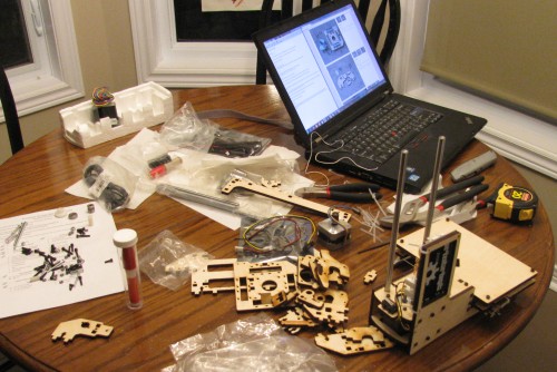
The remainder of this post is terse details with my comments on each step. Not much to see here unless you’re building your own Printrbot Simple. This was the first of three nights I took to do the build (a bit at a time) – for me it was like reading a good book, I didn’t want it to end so I stretched it out a bit.
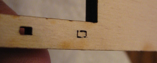
Step 2 – The instructions talk about 5 places you need to separate, mine were all pre-done, I wonder if newer versions of the kit require this separation which would make sense to avoid mis-counting parts to be shipped. In any case, I got to skip step 2. I did find a couple of incomplete holes as pictured below, but they were easy to clear out with a utility knife.
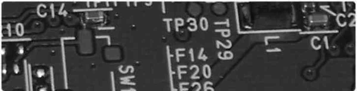
Step 3 – the bearings were unexpectedly oily. One caution that isn’t called out enough in the instructions, the base plate (and many of the parts) are not symmetrical. Look carefully at the pictures to avoid putting things together backwards.
Step 4 – Ugh, a big bag of screws. I need to locate M2 10mm. Well, there are 6 of them, so I did a bit of sorting of the pile of screws to figure out which were which. As an aside, the instructions interchangeably call them screws or bolts. I think they a bolts.
Step 5 – Again, pay attention – board is not symmetrical.
Step 6 – This is one step I’d argue should be done earlier as we need to wait a few minutes for the glue to dry.
Step 8 – At this point I had to go digging around in the screw pile again to figure out what the M3 10mm looked like, and I was inspired.
@printrbot Consider printing a size matching chart on your BOM for the bolts/screws. Sorting through the pile and measuring myself now.
— Roo (@andrew_low) November 24, 2013
I was happy to see this reply.
@andrew_low I should have done this ages ago!
— Printrbot (@printrbot) November 24, 2013
For reference, I tightened the bolts to just ‘squeek’ tight – then a couple of squirks. If you’re putting one of the bolts just into wood like in step 4 be careful not to make it too tight as you can easily strip the wood.
Step 13 – The power adapter is a bit tricky as the photos don’t show it well, and I tried to take a better picture and failed. The nut on the adapter needs to be backed off so the zip tie just fits between the nut and the plastic collar.
Step 14 – Make sure you have the ‘hidden’ wiring well pressed down and away from the edges, otherwise you’ll have trouble getting the parts to mate up.
Step 16 – I suggest you attach the extruder cable 1st, then power supply. No need to make the zip ties very tight here, the board won’t lie perfectly flat and tight zip ties will just bend the circuit board.
Step 25 – If you have trouble seating the screws into the lock nuts. (mine were not quite aligned right). Try removing the #1 plate and threading the problematic bolts part way – the mis-alignment should be obvious. Then you can push the bolt upright to align it better.
That was far enough for one night.