In my previous post on Tasmota I was able to make use of tuya-convert which supports over the air (OTA) updating a ‘smart wifi’ device to the Tasmota firmware. Tuya-convert relies on exploiting a defect in the firmware, Tuya has patched this bug and some (many) device manufacturers have started to ship updated versions of the software – and in some cases new, non-ESP based hardware. Thankfully many devices are still based on ESP hardware and many of the circuit boards even have test points exposed that make hooking up a serial adapter possible for someone comfortable with a soldering iron.
The Tasmota doc is a great place to start. The device I’m working on is a Gosund Smart Light Switch SW5. I did try tuya-convert on this and got the id2 response which indicates that there is a newer firmware. Opening up the lightswitch was easy, but you will need T6 torx screwdriver. Once the circuit board was out I could take a close look.
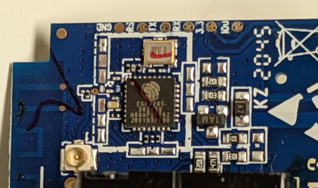
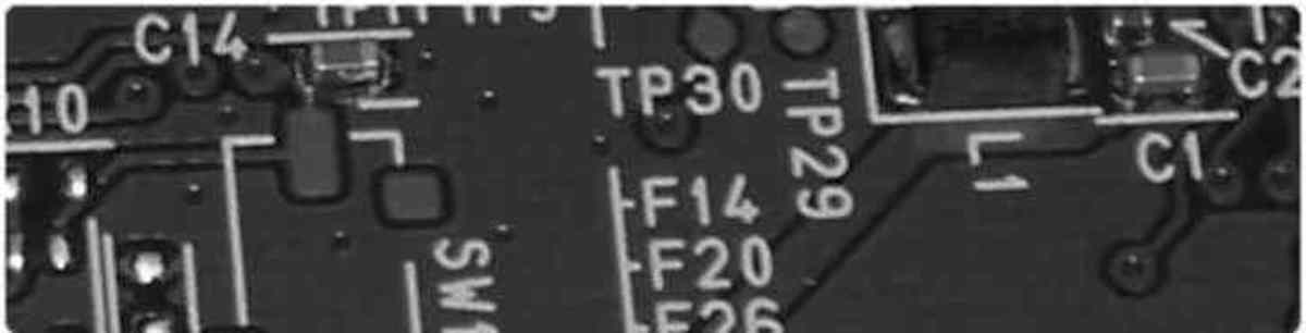
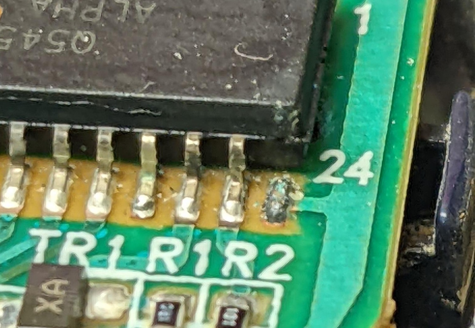
We can see that the chip is an ESP-8285, that will let me find the data sheet and figure out the pin outs. We can also use the Tasmota doc on pin outs as a reference. Right at the top of the image you can see test / solder pads on the edge, these are going to be useful.
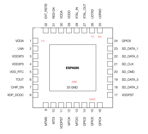
I’ve annotated the chip diagram to show the pins I’ll need to flash the device. It’s hard to tell from the photos I’ve shown so far the scale of the chip, but I can tell you that I don’t have the skills to solder directly to the pins of the chip – I’ll need to use the break out pads on the side of the circuit board. Even those solder pads are very small.
I confirmed based on the data sheet that the break out pads mapped to the pins I had identified on the chip using a multi-meter. The pins on the chip are very small and I was working by feel mostly, but it gave me enough confidence that I could use the break out pads to do the connection.
It is very important to only power the ESP-8285 with 3.3V. If you use 5V you are very likely to break things permanently. Off to eBay I went to pick up what I thought was one of the recommended CH340G serial adapter boards. I later learned that the one I bought did not have a voltage regulator making it unable to supply enough power for the ESP-8285.
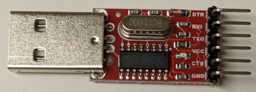
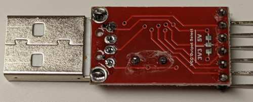
You can see that while this board supports 3.3V or 5V – you must modify the board to break the solder bridge to the 5V and add one to the 3.3V. I was able to verify the voltage was 3.3V after my modification with a multi-meter.
At first I had decided because the break out pads were evenly spaced and about the same spacing as a pin header. I did try this – but got stumped by the fact that if I did hook it up correctly the LED on the CH340G adapter would go out and things didn’t work. This turned out to be due to the fact that this adapter would not supply enough power to the ESP-8285. This approach might work, but soldering to the pads was easy enough and that’s the path I ended up taking.
I decided to use Linux and the esptool to do the flashing. It turns out that I could just use pip to install the esptool.
On Linux, if you haven’t modified your user to be in the right group you may not be able to use the /dev/ttyUSB0 device. There may also be additional things you need to do in order for the adapter to be recognized by the OS. I’ll leave these challenges up to the reader to overcome with some creative use of a search engine.
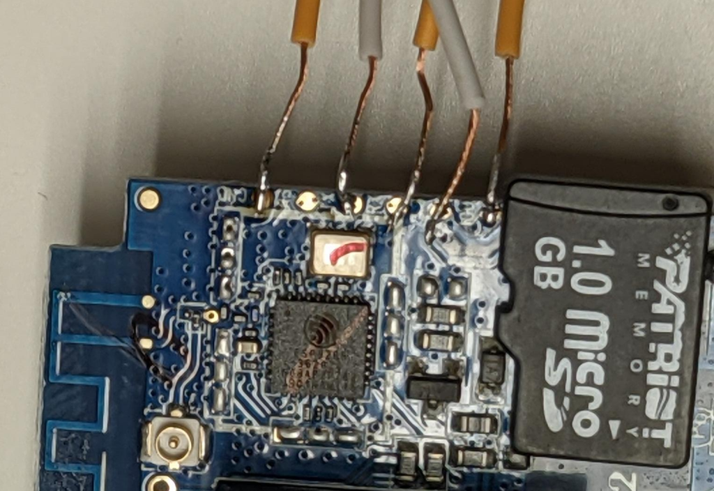
Here are the results of my soldering job – along with a micro-SD card for a sense of scale. This is very small but it’s not too difficult if you use a few tricks. Solder paste on the pads applied with a toothpick are a big help to get the solder to flow. Pre-tinning the wires helps. Working under magnification helped my aging eyes. Make sure the soldering iron is completely warmed up. Also add a little solder to the tip of the iron (pre-tin the tip). With these preparation steps, it should be easy to just touch the iron and the wire to the pad and the solder will flow and you’re good.
Initially I had wanted to avoid soldering, but it turned out to be very quick and easy to do. The reliability of the connection is also superior to trying to press fit the wires – and creating a jig would take a lot more time. In future when I need to flash over serial I’ll just go warm up the soldering iron.
I then decided the correct wiring to perform. Note that TX/RX are swapped. IO0 is pulled to ground to force the ESP into programming mode.
|
|
CH340G -> SW5 3v3 -> 3.3 TX -> RX RX -> TX GND -> GND GND -> IO0 |
It was here where I ran completely into the wall trying to use my cheap eBay CH340G adapter. I did find someone else who’d succeeded flashing the SW5, which gave me hope that I could succeed. It turns out there is a friendly community you can connect with on Discord to talk about Tasmota things. I started a conversation in the #flashing-issues channel and after a short while got some helpful advice.
Now it turns out, I’d been hasty. If I’d done more research I would have found that having a stable 3.3V power supply wasn’t a given for all of the adapters. While the golden CH340G can be had for a few dollars – many of the CH340G adapters do not have a voltage regulator on them and will not work with the ESP devices. Once the Discord folks had kindly educated me on this – I created a pull request to add some additional warnings to the doc (which has been merged).
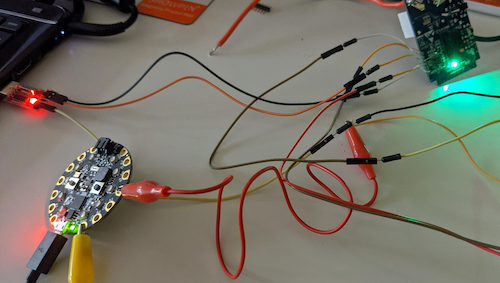
Fellow Canadians might be able to grab one of these CH340G adapters from Amazon, it has the required voltage regulator. In my case I dug through my pile of electronic projects and came up with a Circuit Playground Express, it has an onboard voltage regulator and will easily deliver the ~150mA that the ESP needs (as long as I’m not trying to drive the onboard LEDs).
This changes my wiring diagram. I’ve abbreviated Circuit Playground Express (CPE).
|
|
CH340G | CPE | SW5 3v3 -> 3.3 TX -> RX RX -> TX GND -> GND -> GND GND -> GND -> IO0 |
By connecting all the GND lines together I ensure both devices are using the same reference. I’m pulling the 3.3V from the CPE, but the CH340G adapter is being used for the programming. This worked like a charm, but was a mess of wires.
Now that I have stable power, I can follow the steps.
1. Backup firmware
|
|
esptool.py --port /dev/ttyUSB0 read_flash 0x00000 0x100000 fwbackup.bin |
Unplug the connections and do them again – (power cycles the setup)
2. Erase flash
|
|
esptool.py --port /dev/ttyUSB0 erase_flash |
Again, reset the world
3. Upload tasmota.bin – make sure you get the right firmware.
|
|
esptool.py --port /dev/ttyUSB0 write_flash -fs 1MB -fm dout 0x0 tasmota.bin |
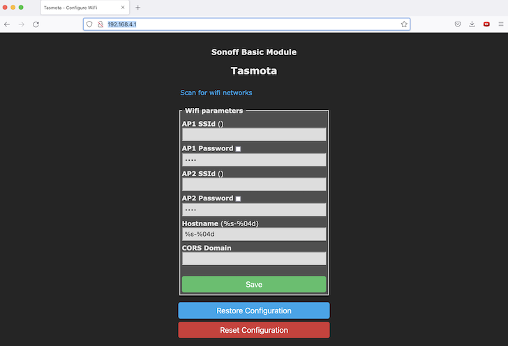
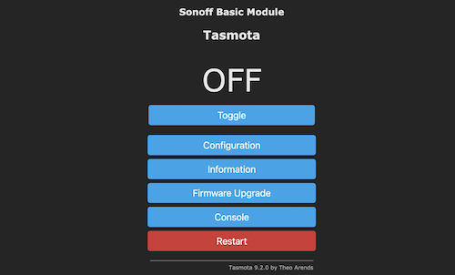
Now you can test your work by providing only power (GND and 3.3v) to the SW5 device to see if the Tasmota firmware starts up ok and offers a WiFi access point (tasmota_XXXXXX-####). You can even go through the initial setup and get it connected to your network.
After I’d gotten my SW5 running Tasmota, I then re-assembled the actual light switch. I found that you had to carefully tighten the screws to avoid binding the switching action. I then temporarily wired this to house wiring to confirm that all of the functions worked as expected. Once things were good, I could permanently install this in my desired location.
I’d referenced flashing Tasmota over serial as the ‘hard way’ – but as long as you can disassemble the device to get to the circuit board, and there are test points you can solder to – it isn’t all that hard. You do need to be comfortable with a soldering iron, and have the right gear to program 3.3V serial.
 I had one of these classic Haupauge remotes which I’d used a long time ago with a MythTV setup. I’ve long ago retired this machine and tossed the remote into the bin. Sadly I didn’t remove the batteries, and when I opened up the battery compartment I saw that they had leaked and corroded.
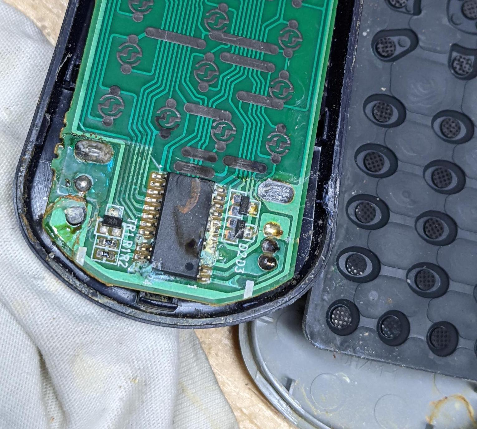
 Using
Using