How To: Migrate from Raid1 to Raid5

Recently I discovered that the iPhoto data was actually stuffed under a deleted user that existed as part of the Mac migration process, this meant it wasn’t being seen by my rsnapshot backup of the active user directory. Fixing the location of the iPhoto library was relatively easy to do, but having an extra 130GB of data to back up immediately ran me into storage problems.

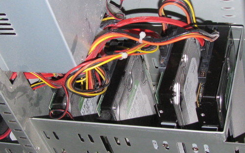
I had setup a RAID1 system using two 1TB volumes, I had decided to split the 1TB mirrored volume into 300Gb/700Gb so I could limit the space used by backups to 300Gb. In hindsight this was a silly idea, and it also made the migration process more complicated. If I had placed the 300Gb volume second, it might have been feasible to move that data somewhere then expand the 700Gb volume to fill the remainder of the drive – but I had put the 300Gb volume first. One day someone will write the utility to allow you to shift the start of a volume to the left (towards the start of a drive).

Instead of sticking with a RAID1 setup, I decided to move to RAID5. While there is a little less redundancy with RAID5, the additional flexibility seems like a good trade off to me at this point. I’ll avoid getting into the religious debate over which type of RAID you should use, or if RAID makes sense at all with large sized drives. Also there are some good off the shelf solutions now such as Drobo or QNAP.

With a project like this it is a good idea to make a plan in advance, then log your steps as you go along. Migration of 100’s of Gb of data will take time, lots of time. I did the work over about 5 days, some of it while on a trip outside the country (remote access!). Here was my plan:

  1. install new drive – ensure system is happy
  2. break mirrored set – run in degraded mode
  3. repartition new drive & unused mirrored drive
  4. create degraded raid 5 (2 drives only)
  5. copy data from degraded mirror onto degraded raid5
  6. decommission degraded mirror & repartition
  7. add volume to raid5 set

I also was careful to check that the new volume had the same capacity as the other two having been bit by that in the past. (I used fdisk -l /dev/sde to get the stats of the drive) Continue reading “How To: Migrate from Raid1 to Raid5”

Surface Mount Soldering: Repair Harmony 659

My friend Trent gave me a pair of broken Logitech Harmony 659 remotes. I bought into the programmable universal remote ages ago when I purchased a Pronto TSU 2000 – a remote I still use regularly to drive my home theater. I’ve watched with interest the Harmony remotes become more popular and lower cost and have often encouraged people to consider getting them. Having a remote control that everyone in your family can understand how to use means better use of the audio / video system you have. I was really pleased to get these two remotes and figured I could fix both of them.

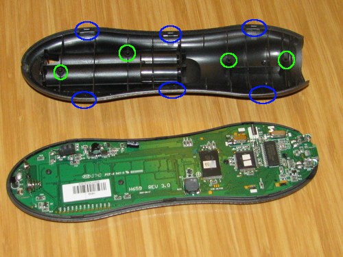
The first step is opening the remote. There are four screws indicated by the green circles in the picture at the top of this post. Two of the screws are inside the battery compartment. Then there are 6 tabs the clip the top and bottom together – indicated with blue circles. A putty knife and some gentle pressure should get the remote apart without any damage. For things like this it’s important to take your time and be persistent (but not too forceful).

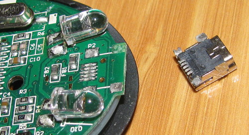
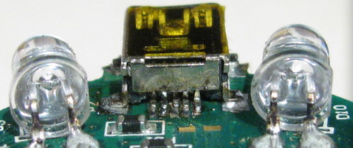
I have two broken remotes. One has a non-responsive keyboard, the other has the USB connector busted off the circuit board. It would probably be fairly simple to combine the two into a single working remote, but that would be taking the easy way out. In the picture above you can see the broken off mini-USB connector. One of the pads has come off the circuit board entirely and the remainder have broken lose of the solder connections. I suspect this failure was a combination of a poor soldering job at the factory, and accidental use of extra force on the connector in normal use.

Prior to doing this repair I had not done any surface mount (SMD) soldering. I went to youtube to learn a few of the techniques for how to do this successfully. I wasn’t working quite at the same scale as is possible, but this was well beyond doing a single pin at a time. Basically the technique is to spread some flux, and drag a loaded soldering iron tip over the pins.

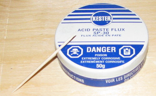
I’ve got a reasonably nice soldering iron now, but I lacked many of the other useful tools such as a a flux pen or loupe. I did have handy some flux I’ve used for soldering copper pipe and a toothpick to apply it with. It worked fine – but don’t do as I did. It turns out that “Kester SP-30 is too corrosive for electrical or electronics soldering applications“. Ok, well lesson learned about making do – I’ll have to see what I can do about cleaning any residual flux off the board.

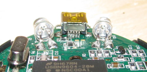
Above you’ll see the result of my first attempt. From a distance it appears to be all good. However, with a bright LED flashlight and my digital camera with 20x optical zoom told a different story.

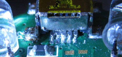
Close, but not quite. There is some visible bridging of the solder between the pins. So clearly this wasn’t going to work and I needed to start over.

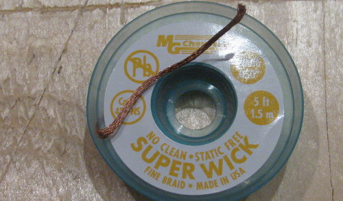
I used some solder wick to remove the old solder. This is a fine copper braid that you heat up in contact with the solder and it sucks up the solder and leaves a clean connection. I should have done this from the start – cleaning off all of the old solder. The result was nice clean solder pads ready for another try.

This time no bridging, just enough solder to get a contact and no more. It’s not as pretty as I’d like it to have been but it appears to work just fine. While this was a bit finicky, it wasn’t really that hard to do. I’ll be a lot braver about dealing with SMD parts in the future.

Initially I had some problems getting it to appear under Linux. I was able to A/B test the other broken unit (bad keypad) as it has a working USB port (very nice to have more than one to do comparisons with). So I started thinking that maybe there was a problem with my soldering work after all. Then I found some instructions on getting the remote into “safe mode”: With no batteries installed, hold the OFF button, plug in USB connection to computer. Once I did this, the remote did show up just fine under Linux. The only weird thing was that after the one time, it showed up even when I didn’t invoke “safe mode” – maybe that caused something to get reset? Before you think your Harmony is broken, try “safe mode” – it might just fix things for you.

I did flip over to Windows XP to run the Harmony software to actually program the remote. Later I may experiment with the Linux solution for working with the Harmony remotes.