It seems I’ve been doing a lot of posts about OpenWRT lately (see my Network category). I guess it’s been a bit of an area of interest for me, and I’m having fun learning about it. With the importance of internet connectivity, having a strong home network makes a difference so it’s a worthwhile investment.
In my previous post on adding a dumb AP (access point) I covered how to extend your network with a second OpenWRT router configured to provide just WiFi access, delegating all of the other functions back to the main gateway. I’d also previously talked about adding additional WiFi networks to support Guest and IoT. In this VLAN post we’re going to combine both of these things.
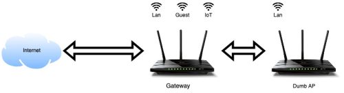 This is where we’re starting, two Archer C7 routers both running OpenWRT (one is version 22.02 and the other is 23.03). The main router I’ll call ‘gateway’ is the hub, acting as my DNS, DHCP and Internet connection. The Dumb AP is just extending my WiFi network – but only has the regular lan network right now. There is a direct cable connection between the two devices (but they are on different floors of the house).
This is a pretty lengthy post, and it is step-by-step so it may seem like a lot. There are really only 4 steps.
- The actual VLAN setup is very easy – we define VLANs on the two routers using the same numbers.
- We use ‘tagged’ traffic on the port that connects the two routers to allow multiplexing different networks over a single cable.
- We create additional WiFi networks on the dumb AP.
- Then we bridge those new WiFi devices to the VLANs and the traffic flows.
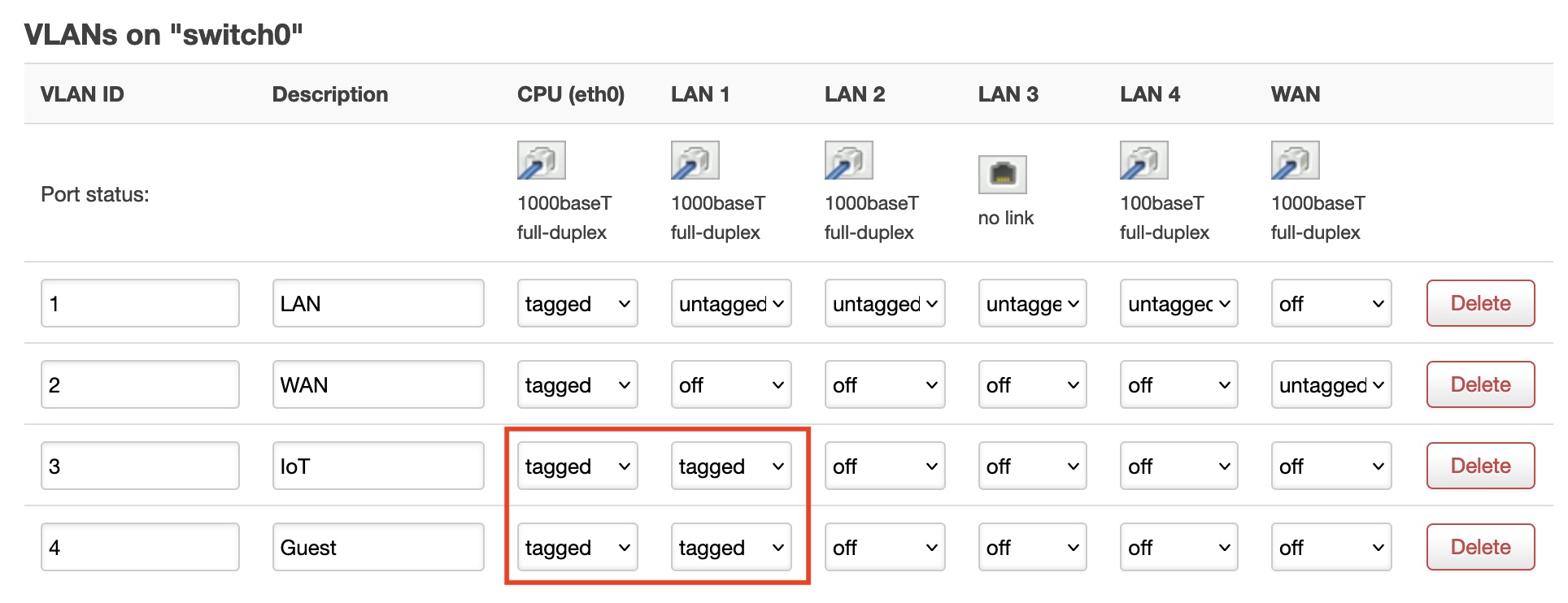
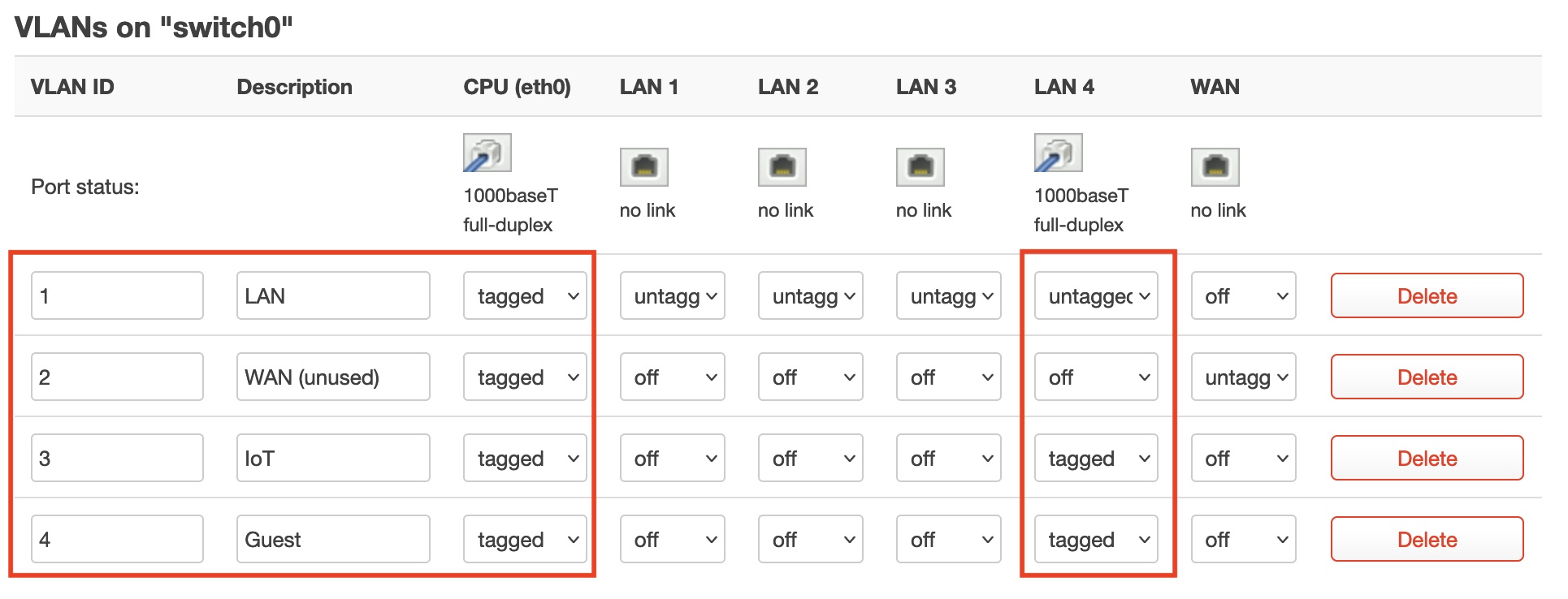
We’ll start by adding some VLANs to the gateway router using the Network->Switch menu on the Web UI.
 A normal OpenWRT install already has two VLANs defined (1 and 2). I’ve given them descriptions (LAN, WAN). My two new VLANs are 3 and 4, and I’ve named them IoT and Guest.
I know that the Ethernet connection to my dumb AP is on the port LAN1, it may be worth verifying that you know which port by disconnecting the cable and verifying that you cannot see the dumb AP anymore on the network. Now that we know which port, let’s modify the gateway to flow VLAN traffic there.
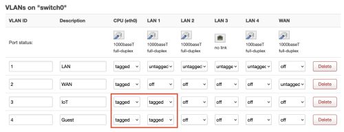 I’ve highlighted in red the changes. I’ve indicated for both of the new VLAN networks that the CPU traffic is tagged, and I’ve tagged the LAN1 traffic. You might also notice that the VLAN 1 (LAN) traffic on the LAN1 port is untagged. We’re taking advantage of an OpenWRT feature that allows untagged and tagged on the same port. We leave the normal LAN traffic untagged as that’s the network we’re using to configure things – but we flow IoT and Guest traffic (none currently) as tagged data to the access point (AP).
So far it seems like I haven’t broken anything because I can still talk to the AP over the connection.
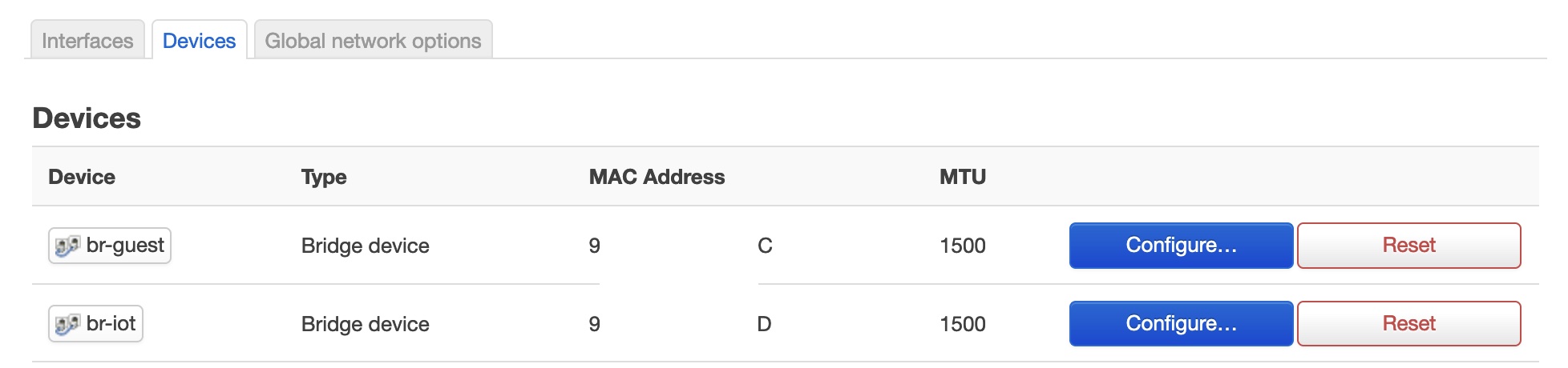
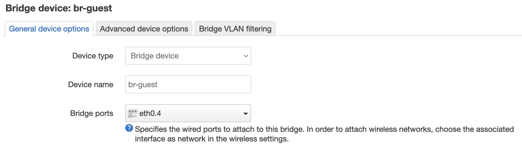
Still on our main gateway we are going to configure the br-guest and br-iot bridges to the VLAN port(s). We’ll use the Web UI again, Network->Interfaces – selecting the Devices tab.
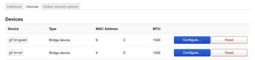 This is of course assuming we’ve set up the Guest and IoT networks as I wrote about, if you’ve used different names then this will be slightly different. Let’s use the
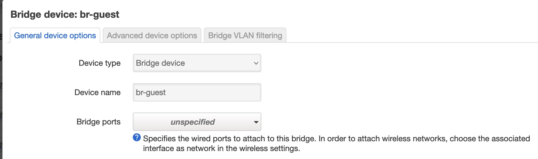
 br-guest device as an example, but we’ll need to do the same to each of the WiFi network devices.
 You can see it is not currently bridged to any VLAN, we’re going to change that and specify VLAN 4 which we will be using as the Guest VLAN.
 Once we’ve got this setup for both network devices (br-guest and br-iot), we are done on the main gateway and can move to the AP. The gateway will now try to flow guest and IoT traffic over the LAN1 port, but the AP on the other side doesn’t know what to do with it.
On the AP first we will rename the WiFi network(s) so we remove it from use by any of the devices in the house. I’m using a single SSID across multiple networks/APs and allowing each device to figure out which channel/AP to connect to. Thus my “home-net” SSID is used for both the 2.4GHz and 5GHz networks, and across every AP. Let’s rename SSIDs on the AP we’re working on to have “home-netx” so we don’t have any weird issues as we are configuring things. After this change is applied, we should see that there are no devices connecting via WiFi to this AP.
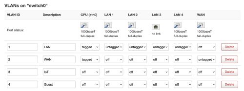
Similar to the main gateway – we’re going to create the same VLAN networks on the AP. Using the same numbers is important, the number is how OpenWRT knows how to match up the network traffic.
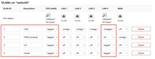 I’ll mention again, this is the Web UI on the dumb AP –
 Network -> Switch that we’re working with. The physical cable is connected to the LAN4 port in my case. Changes we’re making are outlined in red. We’ve added the two VLANs using the same numbers as on the gateway, tagged the CPU traffic, and used a mix of untagged and tagged on the LAN4 port.
The untagged VLAN1 (LAN) traffic on port LAN1 allows us to continue to communicate with the dumb AP. At this point we’re almost done the VLAN setup, but we need to now add the WiFi networks and create the bridge devices we are going to associate with the VLANs.
For the most part we will use a very similar approach to what we did in the guest network post I wrote. We can skip the DHCP and Firewall setups since we will be relying on the main gateway to take care of those aspects, this still continues to be a ‘dumb’ AP.
Let’s move slowly and add a single additional WiFi network, then repeat for the others. For this we’ll move to the CLI because that’s what I did previously for the guest network setup
1 2 3 4 5 6 7 8 9 10 11 12 13 14 15 16 17 18 19 20 21 22 23 24 25 26 27 |
# Configure network uci -q delete network.guest_dev uci set network.guest_dev="device" uci set network.guest_dev.type="bridge" uci set network.guest_dev.name="br-guest" uci -q delete network.guest uci set network.guest="interface" uci set network.guest.proto="static" uci set network.guest.device="br-guest" uci set network.guest.ipaddr="192.168.1.2" uci set network.guest.netmask="255.255.255.0" uci commit network /etc/init.d/network restart # Configure wireless WIFI_DEV="$(uci get wireless.@wifi-iface[0].device)" uci -q delete wireless.guest uci set wireless.guest="wifi-iface" uci set wireless.guest.device="${WIFI_DEV}" uci set wireless.guest.mode="ap" uci set wireless.guest.network="guest" uci set wireless.guest.ssid="guest-netx" uci set wireless.guest.encryption="psk2" uci set wireless.guest.key="SECRET" uci set wireless.guest.isolate="1" uci commit wireless wifi reload |
This is almost identical to what I did in the previous post on guest network setup, but there are a few important changes. The value for network.guest.ipaddr is set to 192.168.1.2 – the ‘1’ is for the guest network, and the ‘2’ is the same as the IP of my dumb AP. What I’m trying to do here with the IP address is reflect the address of the AP, but put it on the guest network. I’ve also set the SSID to have an ‘x’ on the end to avoid confusion until I’m ready to make this real.
A bit more on IP addresses here. The main ‘lan’ network is on 192.168.0.x – the gateway openwrt has address 192.168.0.1. The dumb AP has address 192.168.0.2, and when I declare the guest WiFi bridge on the dump AP I give it 192.168.1.2. Hopefully this symmetry makes sense to you.
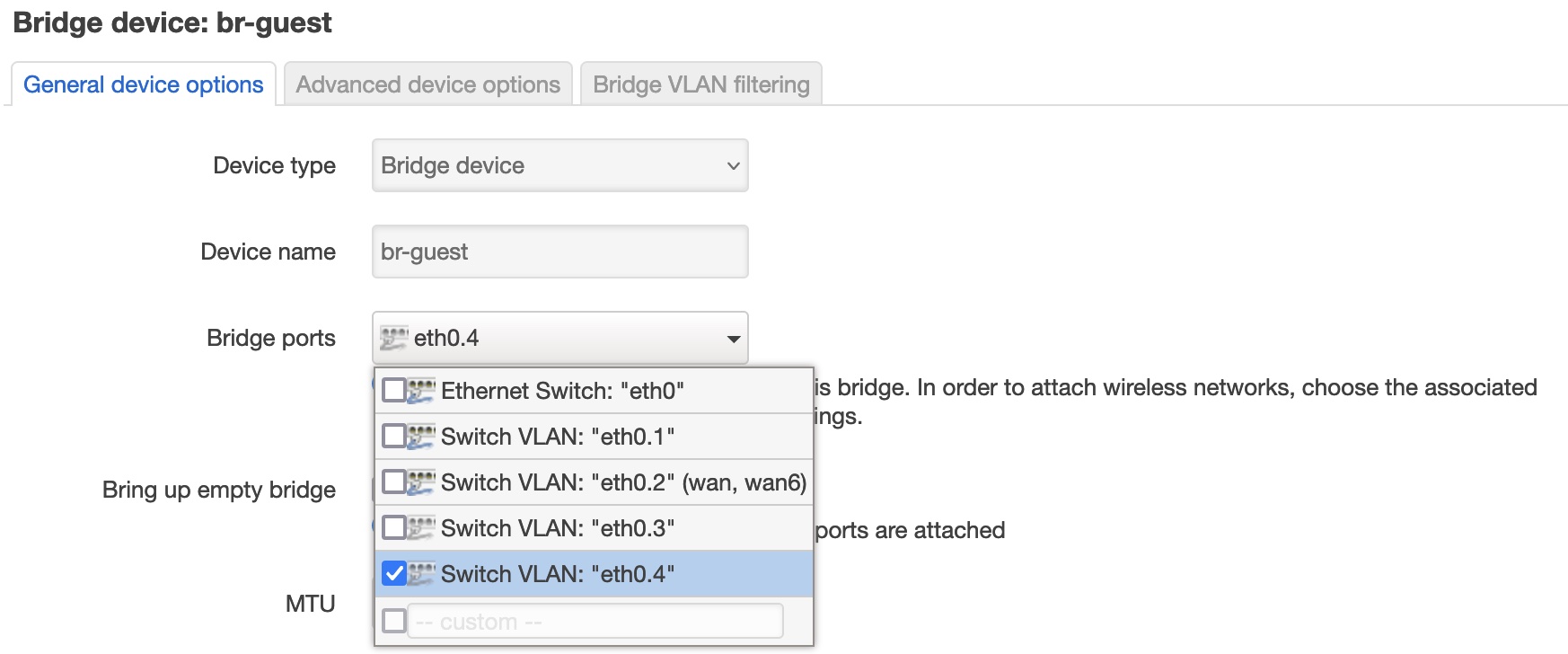
Now just like on the gateway we have to modify the br-guest to link to the VLAN4 network – this will flow packets back to the gateway via the tagged switch setup. On the Dumb AP let’s modify the Network -> Interfaces [Devices], selecting the br-guest device we just created.
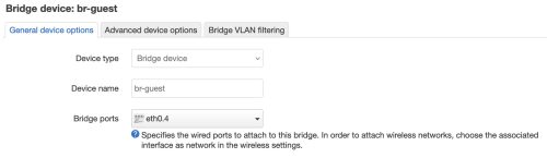 The port eth0.4 maps to the VLAN4 that we’ve declared is the guest network.
Now we can try connecting to the guest network we’ve just configured. Connecting to “guest-netx” gives us an appropriate guest network IP.. and shows the ‘router’ as our main gateway! This seems correct (happy dance).
All that is left is to add the other WiFi networks following the same pattern. Once that is done (and tested) we can rename the networks to the normal names (ie: home-net) and put this AP back into full production.
While my guest network is used sparingly – my IoT network will benefit from having more range via the secondary APs.
In theory – I could get away with a non-direct link between the two OpenWRT devices – most unmanaged switches will deal with things correctly, but YMMV. I’ve taken the safe path and used a direct connection because it was easy with my physical wiring. If you have managed switches, and you are passing the VLANs through them – then you need to teach them the VLAN information. This is beyond the scope of this write up.
If you’re building this out from a clean slate – I’d suggest numbering your networks and VLANs using the same numbers. Example: VLAN 3 should have network 192.168.3.x — if you look back at my setup – I’ve mixed this up where VLAN4 is on network 192.168.1.x – oh well. I believe you can specify higher VLAN numbers – you are not limited to sequential 1,2,3,4 – I’ll leave this up to others to experiment with.
It would be entirely possible to configure the VLANs entirely via the CLI. For example, on the dumb AP the /etc/config/network file now contains some VLAN declarations
|
|
config switch_vlan option device 'switch0' option vlan '3' option vid '3' option ports '0t 5t' option description 'IoT' config switch_vlan option device 'switch0' option vlan '4' option ports '0t 5t' option vid '4' option description 'Guest' |
And unsurprisingly the bridge devices now list a ‘port’ that points at the VLAN, for example the br-guest declaration below
|
|
config device 'guest_dev' option type 'bridge' option name 'br-guest' list ports 'eth0.4' |
I’ll also leave sorting out how to do this via the CLI up to others to explore.
I need to credit the excellent OpenWRT documentation that helped point me in the right direction – specifically the YouTube video by OneMarcFifty.