I’m a big fan of OpenWRT – partly because it turns a ‘commodity’ router into something a lot more powerful, but also because it allows me to choose the software running on an important bit of hardware. Internet access is almost like air at this point, you want a solid solution you can trust. For me, controlling the software is part of that.
To get good WiFi coverage in my house, I needed more than one WiFi access point. OpenWRT has the idea of a ‘dumb AP’ (access point) that allows you to extend your WiFi coverage with another router. I’ve now got 3 TP-Link Archer C7‘s setup. One is the main gateway and the other two are access points. Two was plenty to get good coverage, three ensures that every corner of the house is solid.
The OpenWRT documentation for setting one up is pretty good, but it can be confusing. If you dig around you’ll actually find a few different approaches as well, but I’ll stick with the one that is working for me.
The doc boils down the basic steps into
TL;DR Here are the important configurations for a Wireless AP router (Dumb AP):
1. The dumb AP is connected LAN-to-LAN to the main router through an Ethernet cable.
2. The dumb AP bridges its wireless interface onto its LAN interface. Wireless traffic on the dumb AP goes to its (Ethernet) LAN interface, and then to the main router.
3. The dumb AP LAN port has a static address on the same subnet as the main router’s LAN interface
4. The dumb AP’s gateway is set to the address of the main router
5. The dumb AP does not provide DHCP service, DNS resolution, or a firewall
Clearly (1) is the physical connection between the two devices. It turns out that (2) is not required for current versions (newer than 21.02). This leaves just 3, 4, 5 which we can accomplish pretty easily.
I’m working with version 22.03, and this is a recap of what I did vs. a walk-through as a made a few errors along the way. First you need to start with the device you want to turn into an access point not connected to your main network. Connect directly to it with an Ethernet cable.
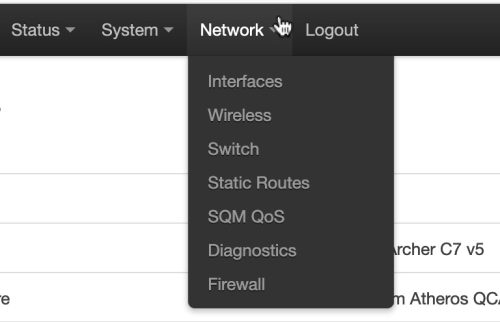
Log in and go to “Network”->”Interfaces” and edit the “LAN” interface.
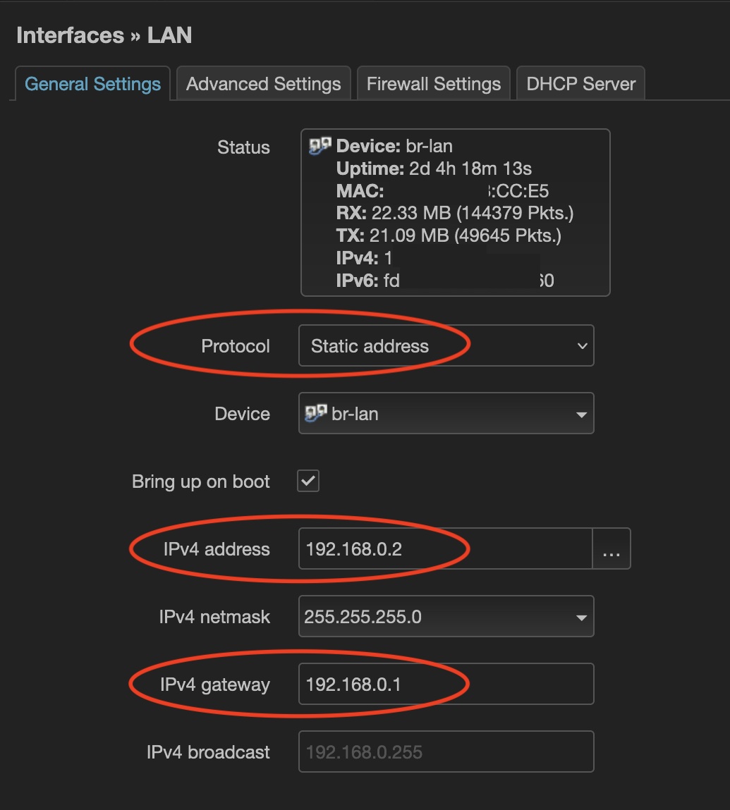 We want to set a static IP address (the Protcol). The IPv4 address you select should be one on your current network that is not part of the DHCP range (pick a low number). The IPv4 gateway should be the IP address of your main router.
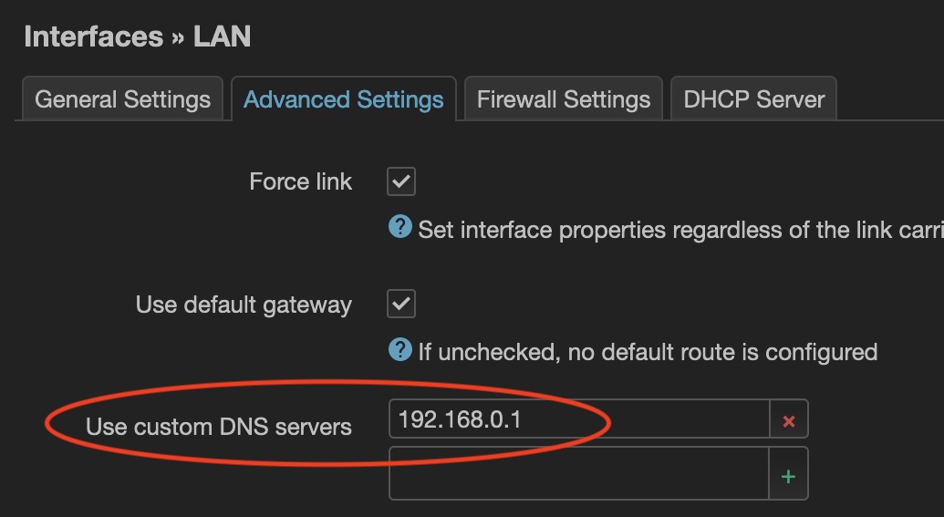
On the “Advanced Settings” tab we want to configure the DNS server to point at the IP address of our main router.
 Next, on the DHCP Server tab we will select “Ignore interface” so we stop this device from trying to hand out IP addresses, the main router has this job.
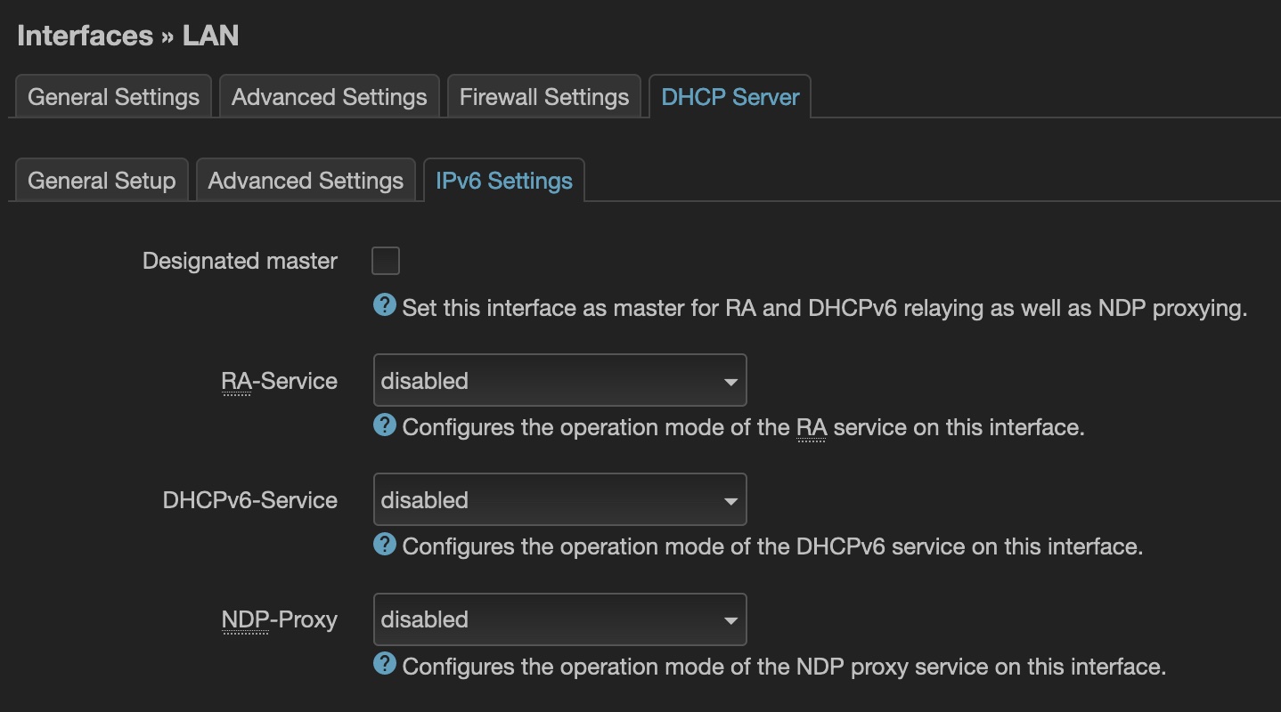 Last we need to go to the DHCP Server sub-tab “IPv6 Settings” and disable all three of: RA-Service, DHCPv6-Service, and NDP-Proxy.
Once this is all done, we can “Save” and “Save & Apply” the settings we’ve made. As we’ve just changed the IP address of the device we’ll likely need to reconnect to the new IP to be able to verify that all the settings have taken hold.
Assuming all is well, we can now connect this newly configured access point to our normal LAN network.
One last thing for configuration of the access point, we haven’t yet disabled the firewall which is not required. Let’s do this in a way that will help us when we upgrade the OpenWRT firmware and modify the /etc/rc.local file to have:
|
1 2 3 4 5 6 7 |
# these services do not run on dumb APs for i in firewall dnsmasq odhcpd; do if /etc/init.d/"$i" enabled; then /etc/init.d/"$i" disable /etc/init.d/"$i" stop fi done |
This will disable and stop the services if they are running. One more reboot and we’re good to go.
Of course, now we have two devices which can offer WiFi service. The access point will forward traffic to the ‘gateway’ which is our main router.
WiFi configuration is just like normal. I would recommend using the same SSID as your main router (and same passwords, etc), but select a different channel. Your devices should seamlessly switch from one access point to the other.
For 2.4GHz WiFI – we are well advised to pick one of channels 1, 6 or 11. There is a good article that discusses why here. Since we have 2 access points we can pick 2 of those 3 channels – so it’s worth looking to see which of the two are least crowded in your area.
On OSX, if you hold down “Option” and click the wifi icon on the task bar you’ll be presented with additional options. Pick “Open Wireless Diagnostics…” then immediately use the Menu bar to open “Window”->”Scan” – this will present you with the list of networks that your OSX machine can see. Moving around your home you can do a rudimentary network scan.
For 5GHz WiFi there are more channels, but the advice is the same. Pick non-overlapping channels. Make sure to set the country code to unlock the channels which are allowed in your country. I wasn’t able to use channel 100 until I did this, so it’s good to configure the country under the Wifi device “Advanced Settings”.
Bonus activity
As you run this 2nd wifi access point you’ll notice that when viewing it’s status page you don’t always see nice hostnames. This is because the ‘dumb AP’ is delegating much of the work back to the main router / gateway and doesn’t build out the arp table which would contain this information. There are some solutions where arp-scan and fping are used to get this information. While this works well, it doesn’t cover IPv6 addresses. The other downfall is that you have to install additional packages.
A simpler approach is to use scp to regularly copy the /tmp/dhcp.leases file from the main gateway to the dumb AP. The one downside to this is that you’ll additionally see the full list of “Active DHCP Leases” on the dumb AP – something that it is not managing at all as we disabled DHCP.
Neither solution is perfect, I’ll leave this up to the reader to decide which works best.